tribomechadynamics
impact hammer
In my junior year at Rice University, I did research for the Mechanical Engineering department’s Tribomechadynamics (TMD) Lab!
‘What is Tribomechadynamics? In short, it’s a new field that has emerged from the confluence of structural dynamics, contact mechanics, and tribology.’ (this was pulled directly from the lab webpage lol - brake.rice.edu)

One aspect of study is the behavior of joined metal interfaces, such as this combination Brake-Ruess Beam.
Many of the lab’s activities included measuring the variability and repeatability of these frictional interfaces, and creating computational models for them.

Other area of interest include bodies with complex geometries, such as this Audi brake knuckle.
Which of course is incredibly funny, because our professor’s name is also Brake!
The indelible Dr. Matthew Brake 😤

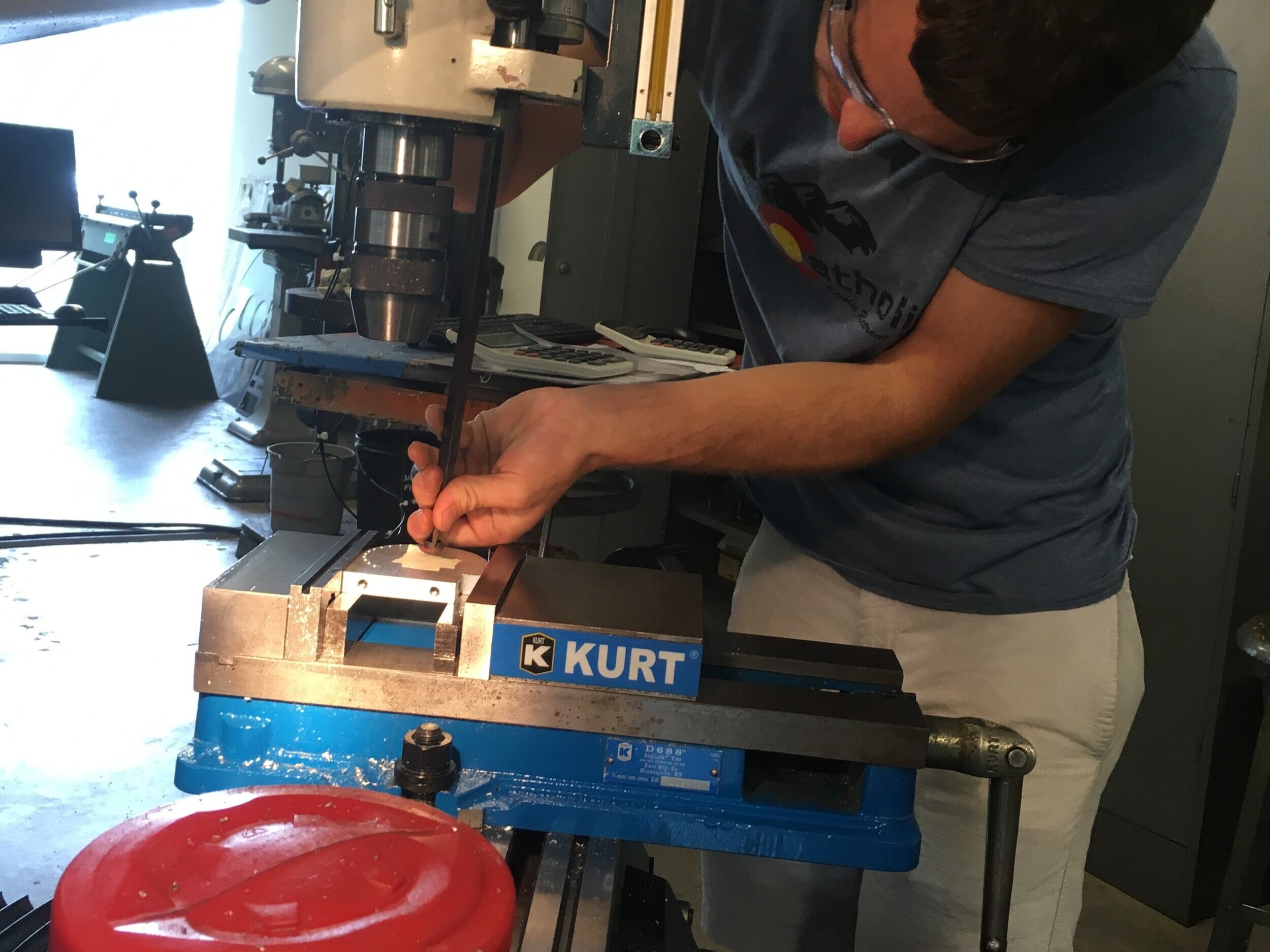
The tool visible in the previous photograph is a modal hammer, used to help measure resonance and modes of these metal structures! To characterize models, etc.

These hammers are designed to be handheld and swung every which way, which limits the repeatability of strike impulse and placement. Therefore…

My project was to design repeatable modal hammer strike system.
The method that made most initial sense was a pendulum, so I drafted some early CAD - keep in mind I was very inexperienced with Solidworks at the time.
(I didn’t have a fitting image here, so enjoy some Gon!)


Several very funny-looking models I made in Solidworks (definitely reflective of my inexperience with the software at the time). Going from left to right, top to bottom:
Trying to fit some flange bearings onto some T-slotted tubing — I initially wanted the whole shaft to rotate with the pendulum
Trying a minimalist design that would require only minor machining work
Moving away from a full-length axle to a small bracket, fixed shaft, and bearings mounted on the pendulum block itself
Exploring using a cam system to push the pendulum to a set height, and then to drop it
A curious, gym equipment-inspired piece to allow for variable drop heights. The pendulum would be pulled up a certain angle past a hole, a retaining pin inserted, then quickly removed when the pendulum was ready to ‘launch’
A more robust frame using T-slotted framing and fittings. The mechanism in the center is something I’ll explain in a bit.

It soon became apparent that with a pendulum design came the inevitability of the modal hammer continuing to swing and repeatedly strike the metal sample after the initial hit.
I needed to develop a catching mechanism that would allow the hammer to swing smoothly and yet be caught in an instant.
Some brainstormed ideas from colleagues included cameras, microprocessors, lasers, sensors, brake discs, and brake calipers. :/

However, I knew there had to be a simpler, purely-mechanical implementation.
It came to me one miserable night in the library. I could use a pair of discs about an axis, one with the hammer mounted to it, and the other as a ‘shield’!
These discs would include overlapping slots arranged in a way to allow a forward swing, upon which a spring-loaded pin penetrates and locks the ‘shield’ disc, exposing the second disc for locking on its subsequent return swing.
In this way, the first disc shields the second from locking before it begins its return swing, hence the names.
Here is a rather, uh, unspirited narration/walkthrough of the system.
(I told you it was a miserable night - was sick and you can definitely hear it in my enunciation)
But yes — hopefully this will be clearer than the sketches!
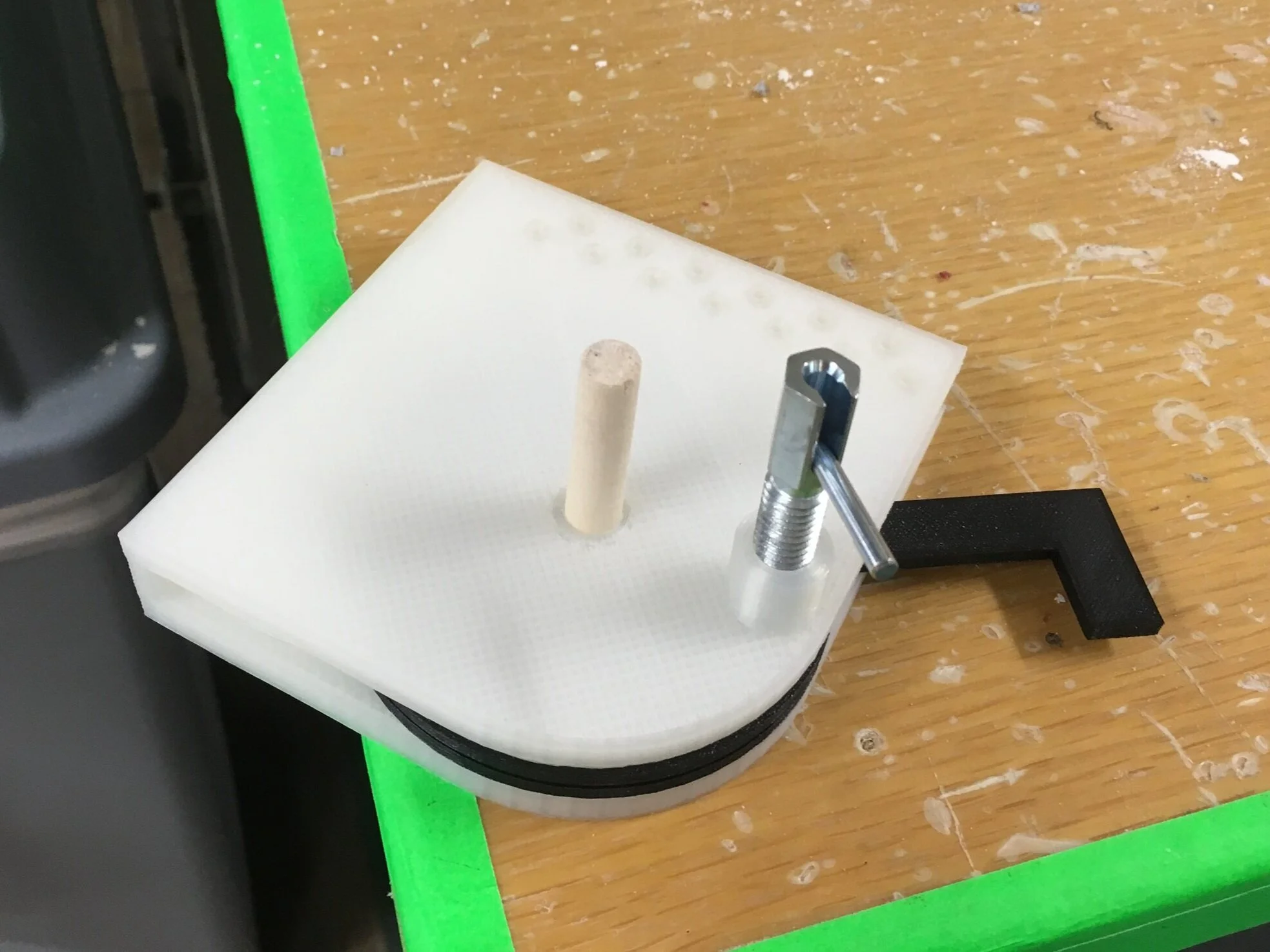
An early proof-of-concept! It’s hard to tell, but both discs are sandwiched inside the white 3D-printed bracket.
(Like a reverse Oreo!)
I used a dowel as an ‘axle’ and the spring-loaded pin is shown installed too.

A slightly more-updated model, with beefed-up walls for durability, mounting points to commercial T-slotted frame fittings, and sectioned into machinable chunks for eventual aluminum construction.

A 3D-printed version of the aforementioned design. One way I was able to keep the assembly compact was by bringing both discs closer together.
Then, to prevent them from rubbing against one another, I added needle thrust bearings to the design, to allow the surfaces to slip without the bulk associated with conventional bearings.

Fully-assembled mockup! Well, as fully-assembled as a mockup can be, anyway.

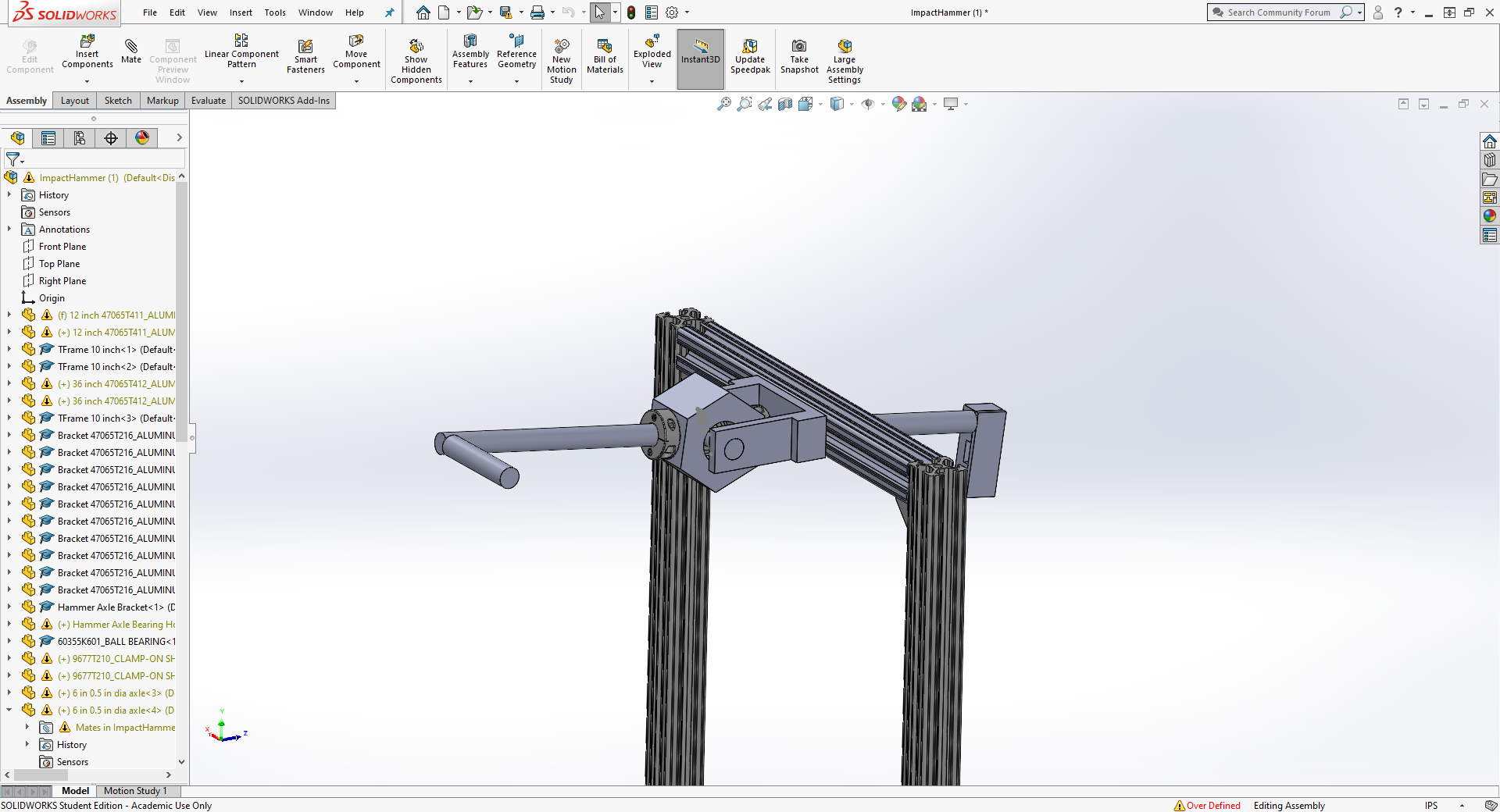
With a working initial concept, I created a finalized CAD model…

Wrote up a BOM, got a figurative blank check from Dr. Brake…
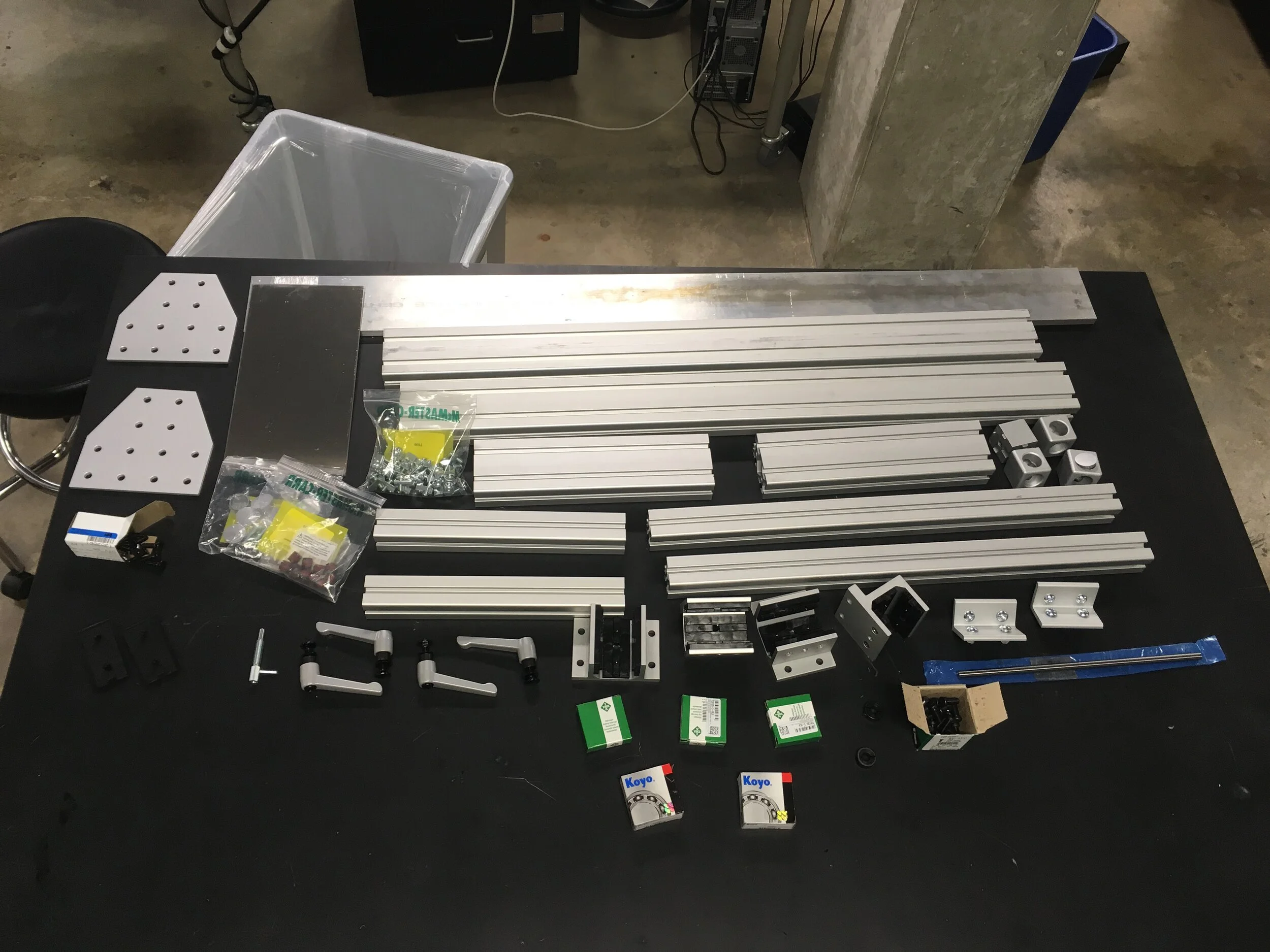
And blew ~$800 on some metal goodies! A bunch of T-slotted framing, fitting, locking handles, brackets, reinforcement plates, bearings, hardware, and aluminum stock for machining the catch mechanism out of.
All from McMasterr-Carr (an engineer’s Toys “R” Us store)!

As previously mentioned, I had sectioned my catch bracket into several flat pieces, for easy machining out of 1/2” aluminum plate. You can see this here, in the disassembled 3DP mockup.

I created drawings for each of the components, then labelled each dimension with Prototrak (the CNC software) in mind.
You don’t just plug in metal and a CAD file and and have the CNC machine work its black magic, but instead have to rigorously define a coordinate system and base all of your cuts and drills on that geometric reference.
Errors accumulate very easily, hence my three sig figs past the decimal point :)))

In addition, I went through and determined which toolhead to use for each action, including what cutting bits to use to cut clearance-fit vs. threaded holes.
Just so machining would take as little time as possible.
Here is Tyler — a grad student I worked with! We worked together over the summer to machine out the catch mechanism walls.
Hope he’s doing well!

The overall bracket went off without a hitch, and I used the school water jet cutter to cut out the shield disc!
I also tried using our plasma cutter, but the torch cuts were way too imprecise to be acceptable.

Here is an ‘open-face sandwich’ look at the bracket internals! I left the hammer disc as a 3D-printed part for now, as I still hadn’t figured out a hammer attachment yet.
The process, as you might be able to tell, is:
Hammer (mounted on gray plastic piece) swings forward, bringing with it the shield ‘disc’ via a slot and pin system.
Near the end of the forward swing, a spring loaded pin enters the small slot on the shield plate, stopping it from rotating further.
The hammer strikes the metal sample and rebounds, briefly aligning its hole (somewhat visible through the shield plate’s slot in this pic) with the now-locked shield plate’s slot
In this instant, the pin enters the second plate, locking it in place as well.
If that paragraph didn’t do it for ya, here is a video of the catch system working instead!
You can hear the spring-loaded pin as it penetrates the pair of discs too.
Note the first swing through, then *pop*, then a swing back, *pop* again, and then no more forward swing.
Here is another short clip, looking at the system internals! You can see the pin extend from the top right direction, down and left through the two plates.

Finally, I needed a way to rigidly mount the hammer to the disc.
‘Rigid’ obviously couldn’t happen anytime while the rubber handgrip was still attached to the hammer, so I sliced it off (without permission oop).

Then I designed a pretty simple bracket to fasten the hammer to an extended hammer disc. I even made brackets for the hammer’s BNC connectors!

With a design in mind, it was back to the ProtoTrak for one last ride.

Setting up the long hammer disc (that no longer resembled a disc)…

Shakycam timelapse of CNC milling…

And boom! Original 3D-printed part alongside its machined aluminum brother!
If you look closely, you might notice the aluminum part has a slightly longer slot cut out! The length of this cut can be changed in any additional copies, and the amount of overlap this slot has with the shield disc’s hole determines how far the hammer is allowed to swing before its motion is arrested.
That was a mouthful. I am sorry.

Finally, to assemble the frame, I cut some threads…

Bolted everything together…

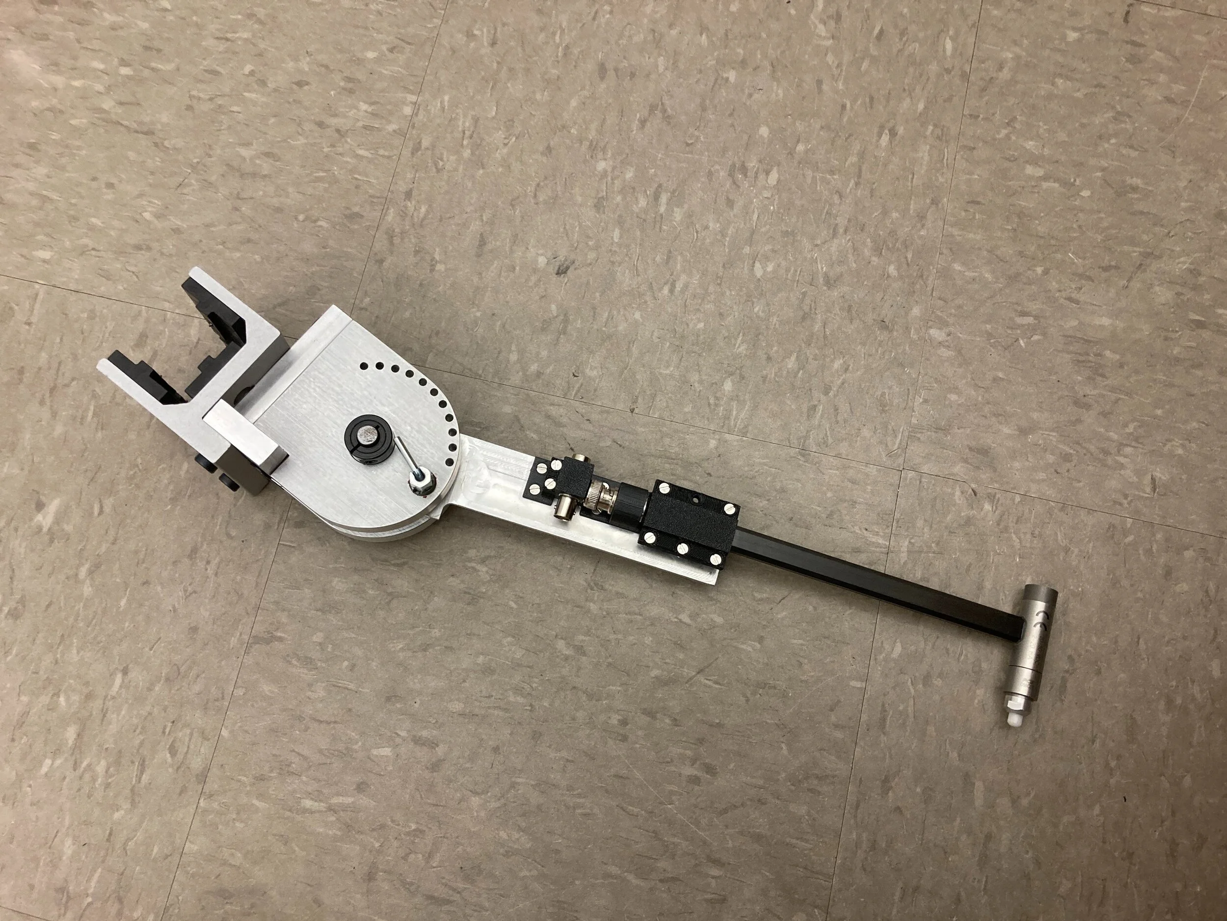
And assembled the hammer catch system. Looks super clean!
Finally, here is the catch system in action! Nidish and I were able to test and read some repeatable data at the end of the summer, so the device was successful!
I couldn’t find footage I took of those, but here is a near-complete test clip of the hammer catch system in action!
What a great summer! I got to build a whole bunch of stuff (S.A.G.A. was created concurrently to this too!), avoid doing any real math, and hang out in Houston!
Finally, it definitely helped me stay in an engineering headspace and keep my skills sharp over those couple of months.
addendum

Incidentally, Dr. Brake referred my project out to the Biomechanical Environments Laboratory at Texas A&M, and I got to speak with Jessica Ezemba about her own pendulum rig!

They were having the exact repeated-hit problem I had designed my setup to avoid, and so it was a fun case of having a perfect match between shortcoming and solution!
Also, their research was to characterize and mitigate impacts leading to Traumatic Brain Injuries, and so as someone who’d had 4 concussions before, I owed it to my fallen brain cells to support this effort <3