Ultracompact dc motor

In my final semester of undergrad, I took MECH 488, a Mechatronics class. And one of our early projects was to create a DC Motor!
Enter Team BRUH - our group for this project - B.R.U.H. of course being an acronym for Brian, Ryan, Uthena, and Hope! - and that little thing we’re holding is our motor

For some brief background, here are the operating principles of a DC motor!
Magnetic fields are generated whenever you run electric current through a wire! (Hence ‘electromagnet’)
When you coil those wires, arrange them around a rotor, and activate them at certain timings,
They will repel permanent magnets (the gray semicircular pieces) and cause the rotor to rotate!
These timings are managed by the smaller rotating object, called a ‘commutator’!
Due to the segmented nature of the commutator, when you touch an electrical current to it via a brush, the rotation will continuously disconnect and reconnect specific coils, magnetizing only those best positioned to repel the permanent magnets, and contribute to the rotation at any given time!
Video courtesy of Jared Owen

Our professor provided us with example motors from previous classes…

… But most of them looked very… hastily built.
I could be much harsher here, but that’s not the point. I saw massive room for improvement, and knew Team BRUH could do better!

My initial instinct was to cheese the whole assignment by replicating this design, but with solenoids instead of pistons!
We’d create not a motor, but an ‘electromagnetic rotary device’ 😂
Unfortunately I had a team of scaredy-cats who didn’t want to cross our professor :(

Going back to *actual* motor designs, one thing I wanted to do differently for sure was to streamline the coil → commutator wiring.
Here, a group had used copper tape for their commutator, and soldered the coil wires straight to it, leaving visible solder points and loose, exposed wire.
The idea I proposed was to run those wires inside of a hollow shaft, something inspired by my Gearbox Project!
Additionally, in almost all the previous classes’ designs, both the rotor and commutator were situated between the pair of bearings. However, I wanted to place a bearing between the coil and commutator, to absolutely emphasize that no wiring ran on the outside and was safely hidden inside instead!

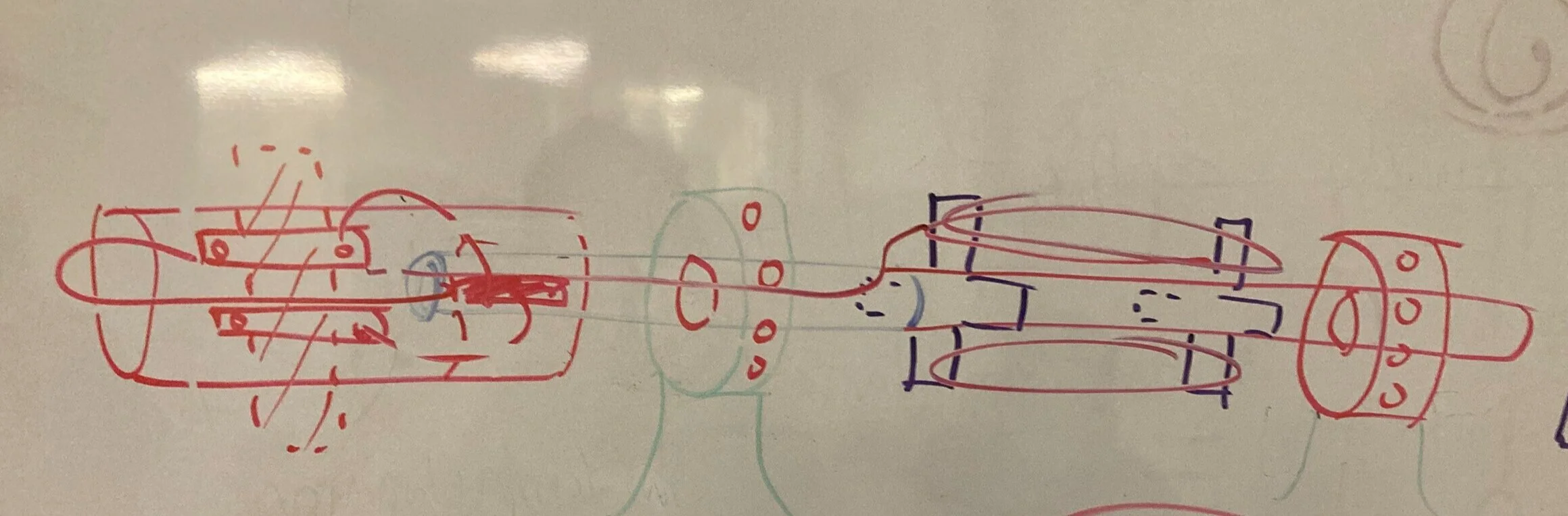
Those dry erase marker sketches were refined into a more coherent drawing. Hopefully this makes a little more sense!
(I bought a drawing tablet! Super happy with it, such a good investment!)

I made some very preliminary CAD, trying to keep the bearings and rotor smaller than 1.375” in diameter. (The next pic shows why)
(also yes I did go and model individual wires feel free to call me a tryhard)

Next, I housed the entire assembly inside of an 1.375” ID acrylic tube. We absolutely weren’t going to build one of those traditional, boxy motors. Not while I’m on the team; We’ve got more pride than that!
The copper looking piece is the commutator, and the two black rectangular pieces are carbon brushes meant to deliver current to it. These both are housed in a custom end cap.
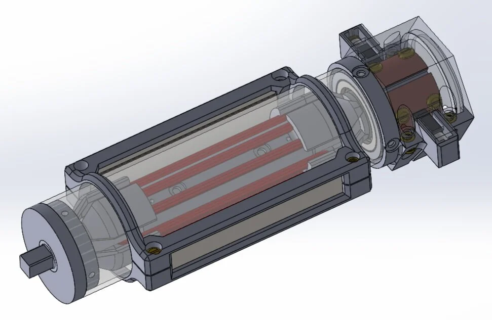
As mentioned before, motors need permanent magnets, to have something to repel off!
So I added a clamp-together style magnet holder (the light gray pieces between the brass screws) to fit around the acrylic tube.
It looks like a space station!

Finally, the design calmed down into a much sleeker package, as shown here! I ditched the bulky carbon brushes and streamlined the magnet mounting solution - I’ll go over these more later!

CAD assembly animation! swag 😎
The first piece I printed out was the rotor! Here I am, having just wound a practice coil at home!
ft. some easily and very-much-avoidable road rash 😣 (I need to stop crashing bikes)
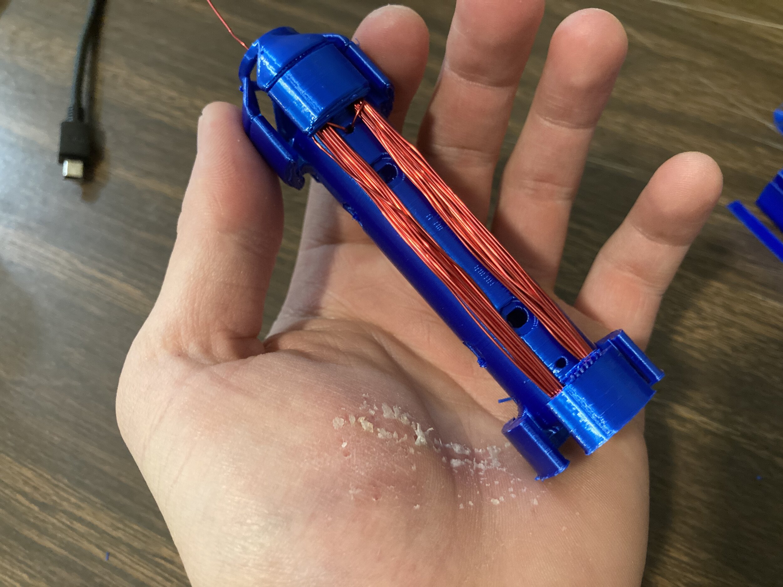
Next, Team BRUH modelled and printed a very rudimentary prototype motor,
Just to verify my admittedly arbitrary rotor geometry would work okay!
The coil-commutator wires are still on the outside of the shaft; at this point we weren’t worried about that yet!

The prototype motor spins!!! Also note the black magnets on the blue panels, I’ll elaborate on them more later!
We bought some cheap amazon bearings for this test, but the rolling resistance was so high, we couldn’t accept them for use in the final version. I ordered new ones around this time.

With our geometry verified, it was time to start machining for the final version!
Here is a 3DP reference jig I made for our aluminum shaft, to be able to easily place and mark holes right where the design needs them - no measuring or guesswork required!

Marking the holes - later punched to create easy drilling indents
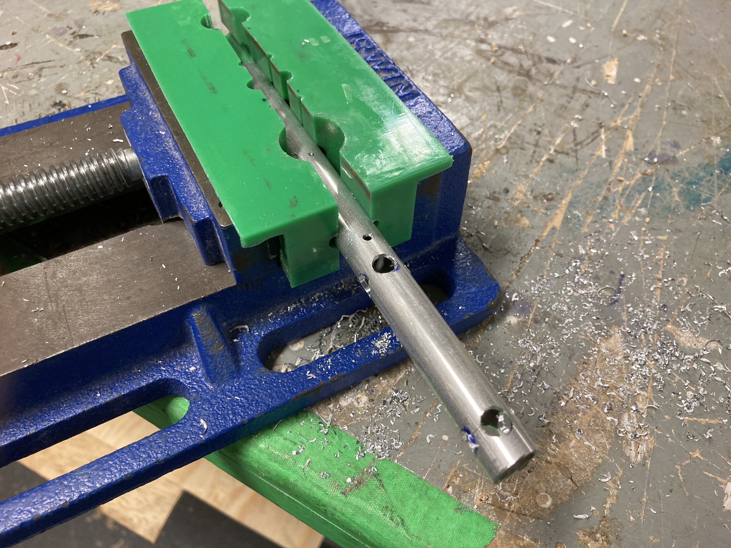
If you look closely, you can see one such punch indent in between the green segment of the clamp.
I drilled two sizes of holes - 1/4” for the wires to pass through with plenty of clearance, and #40, to be threaded for bolting the rotor on later!

I bought a tapping set and threaded out the #40 holes for M3 screws!
(because you better believe Brian Chen doesn’t use glue in projects 😤)

Said M3 brass screws, threaded directly into the shaft!! Big win!
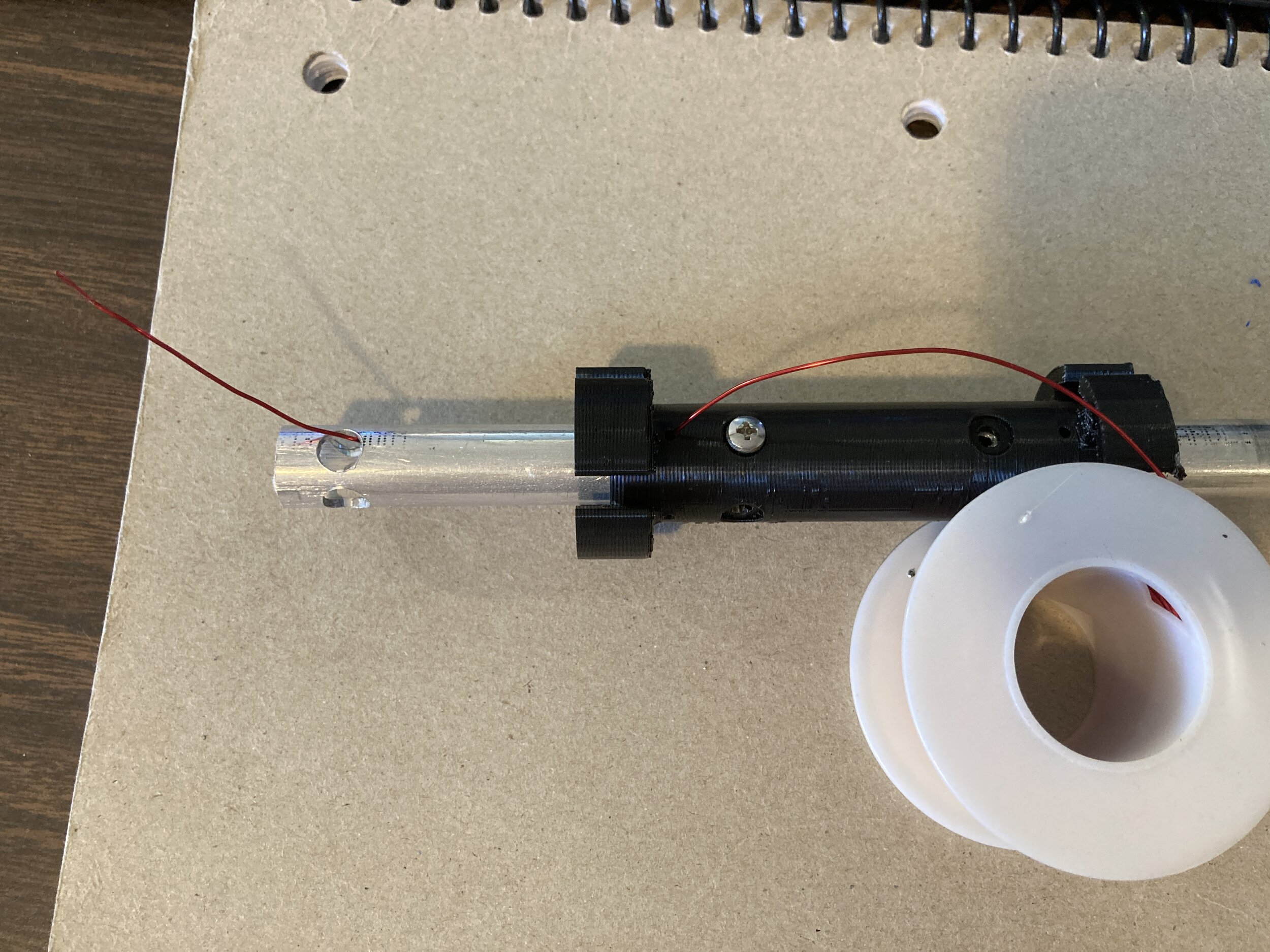
Demonstrating the wire path - I oversized the holes to reduce the chance that any aluminum burrs would scrape or cut the enamel wires, which would ruin the circuit and consequently the entire motor.
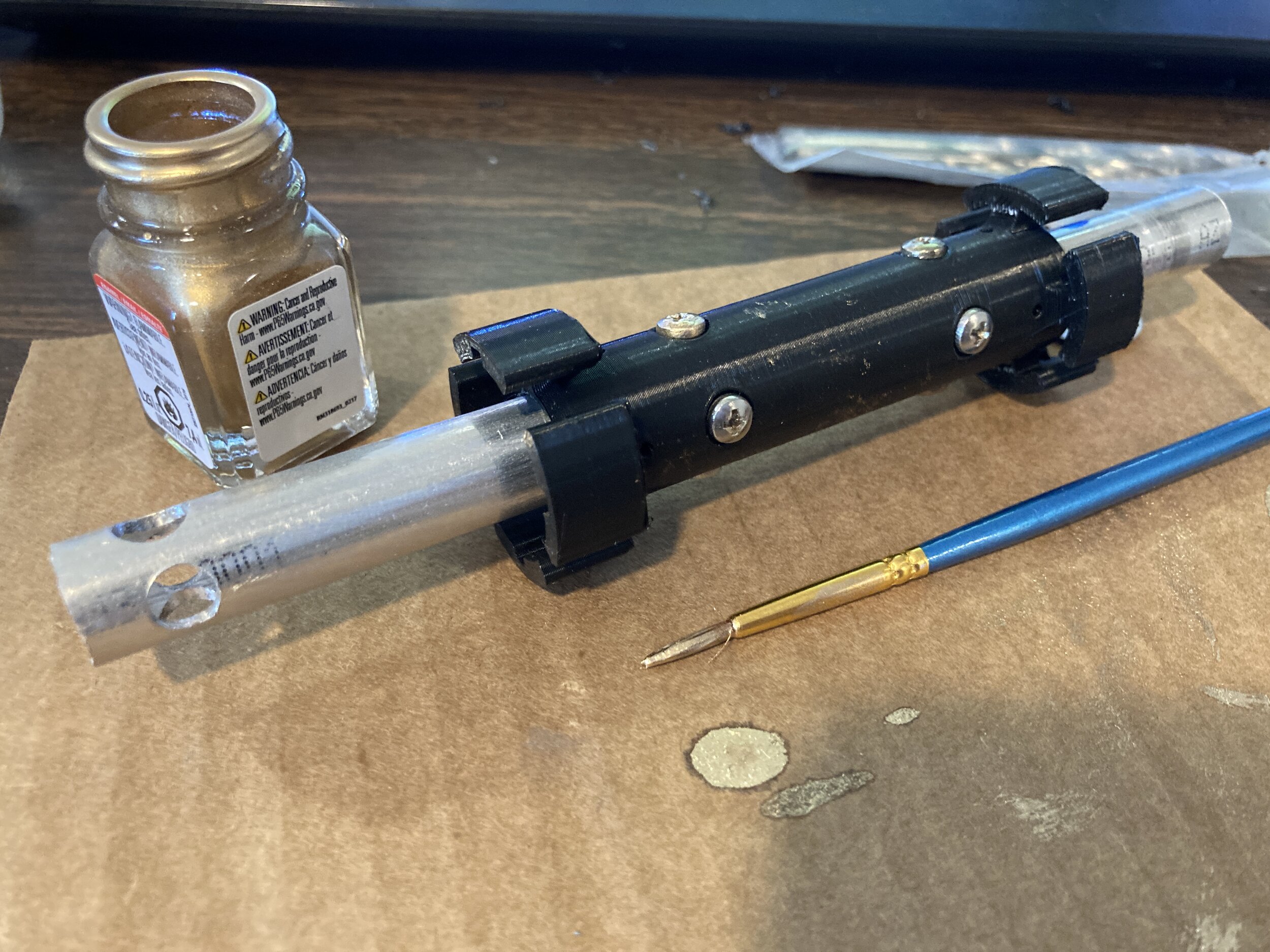
I decided it wouldn’t be financially responsible to commit 16 brass screws on this project (not too expensive but shipping though - 😭), and decided to just use gold paint to color some steel bolts instead

Rotor painted and ready for wire coils! ft. my calluses and slowly healing hand

Those of you paying attention might have noticed, but as early as our prototype motor we had moved away from copper tape…
…and decided to cut commutator pads directly out of copper tube! This provided a much more consistent surface than tape, and with the tube already being round, we avoided having to bend copper sheet into shape like some other groups!
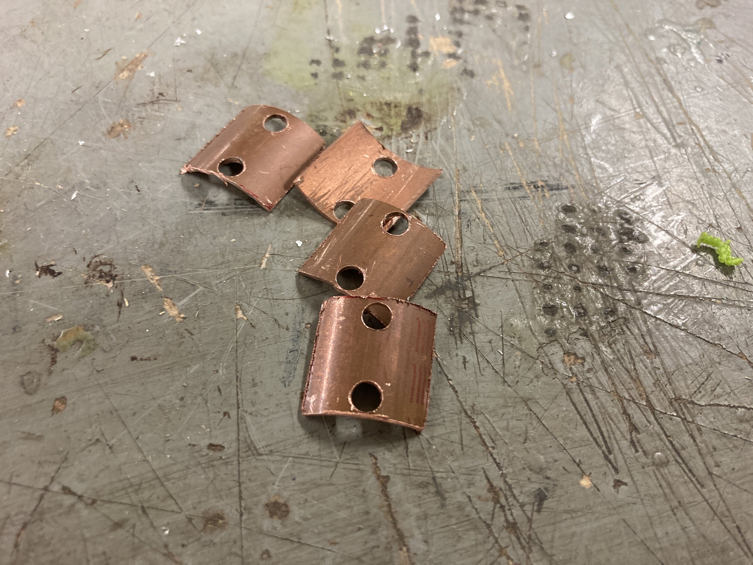
Said commutator pad segments! We would eventually sand down the burrs, though they still look a bit messy in this pic.
Also, keeping with not using glue, I drilled holes to bolt the pads into the commutator.

Mockup of rotor and commutator, all bolted up and waiting on coils! My roommate commented that it looked like a sonic screwdriver - I guess?? ¯\_(ツ)_/¯
Because I had so stubbornly insisted on the bearings being between the rotor and commutator, we had to wait for them to arrive before proceeding further.
Unfortunately, Winter Storm Uri was in full swing, causing us to lose power and a lot of shipments to be delayed. Fortunately, Dr. O’Malley is a saint and gave us an extension.
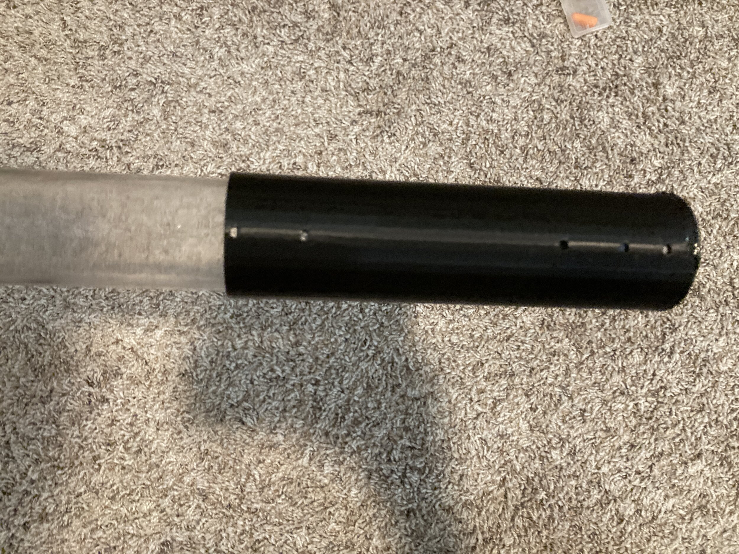
In the meantime, because we *did* have the acrylic tube,
I created another 3DP jig to mark holes and cut the tube to length, just like with the aluminum shaft!
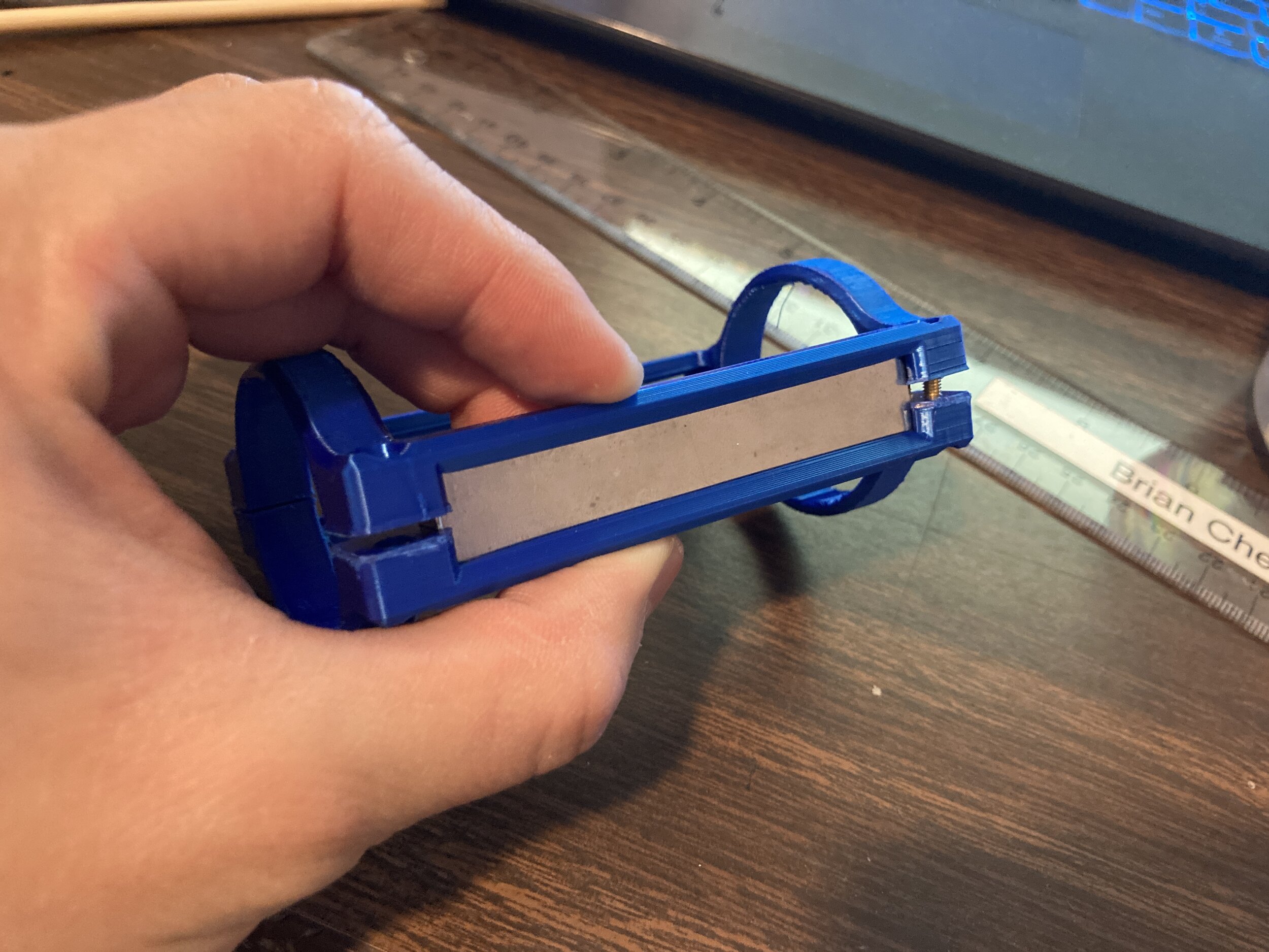
And while a test print of my clamp-style magnet holder did prove successful…

We thought of a much sleeker way to secure the magnets… using other magnets!!

ahaha

Demo of how securely this mechanism holds the magnets!

*Finally*, the bearings arrived! Around 11 days late but they were here!
Pictured here is them being test fit in their mounts, one as an endcap and one as an insert/spacer to stuff into the tube.

Test spin - pretty smooth!

With the bearings arrived, our group hurried to assemble everything.
We all worked together to wind the rotor coils, thread the wire through the holes and shaft interior (no easy task, but I knew we could do it!), and solder them to the commutator pads from the inside!
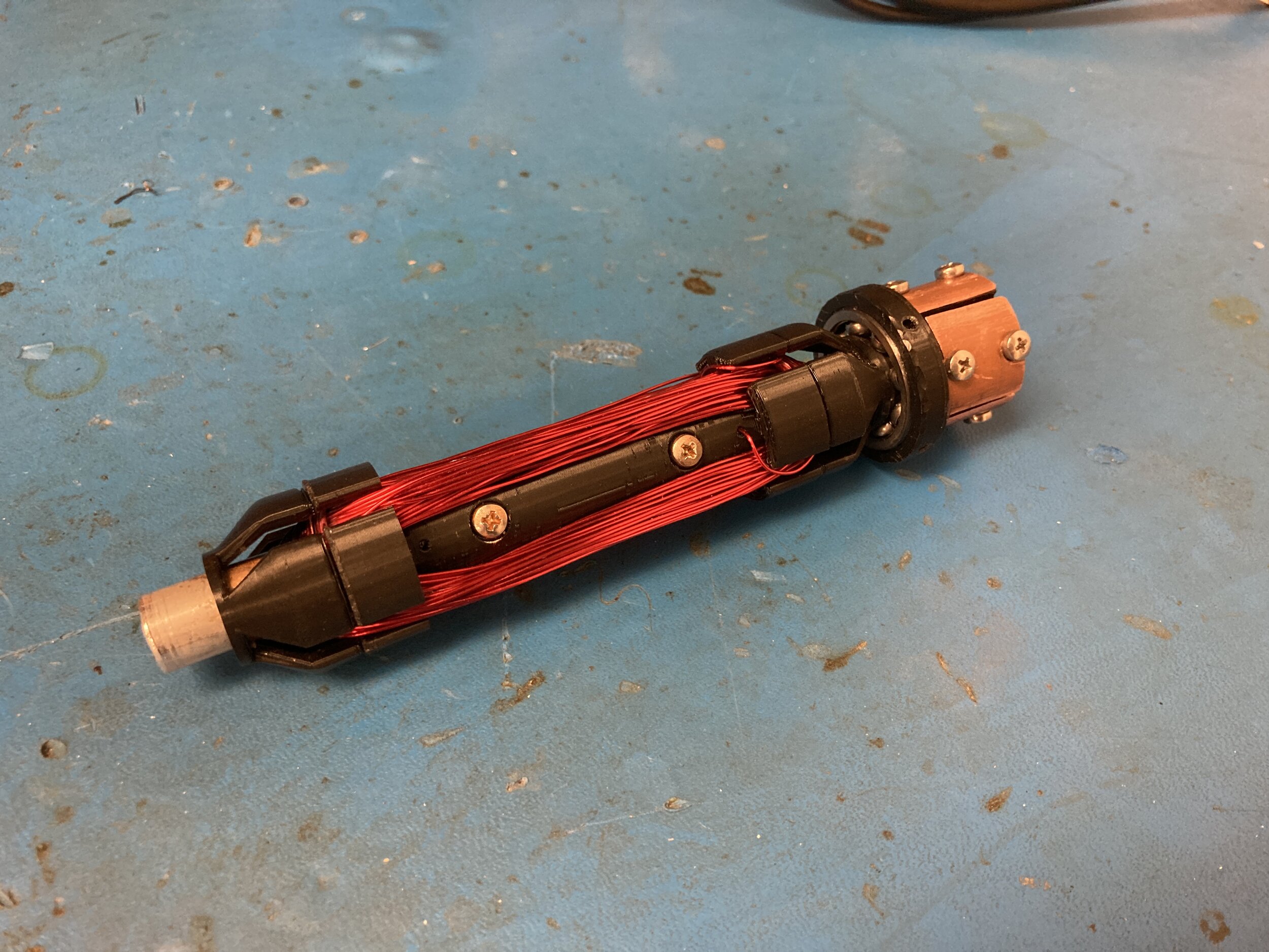
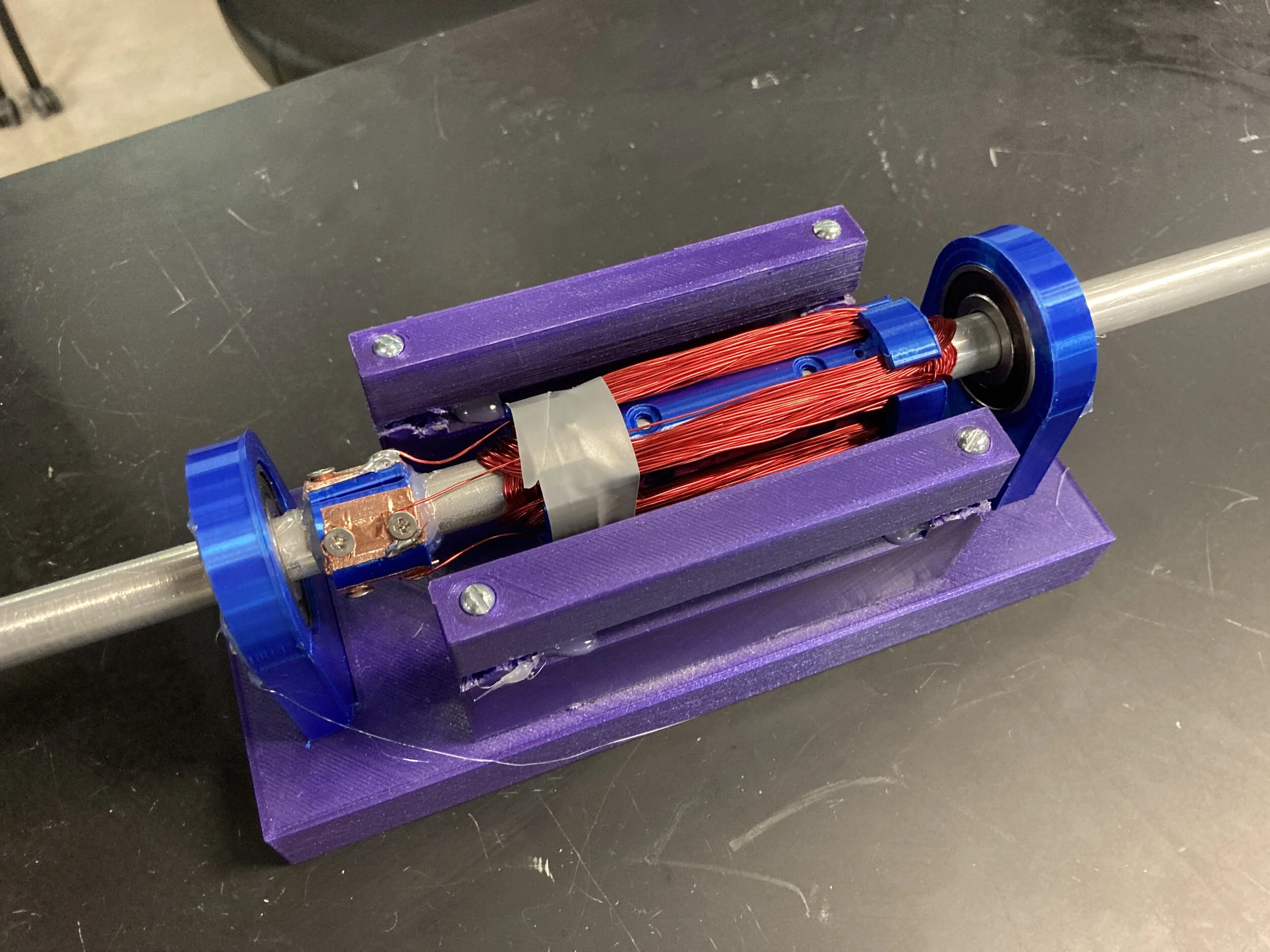
All finished up! The solder joints are completely invisible from the outside!
I think the extra effort in hiding everything inside really paid off! This thing looked so clean!!! We were all very happy with it.
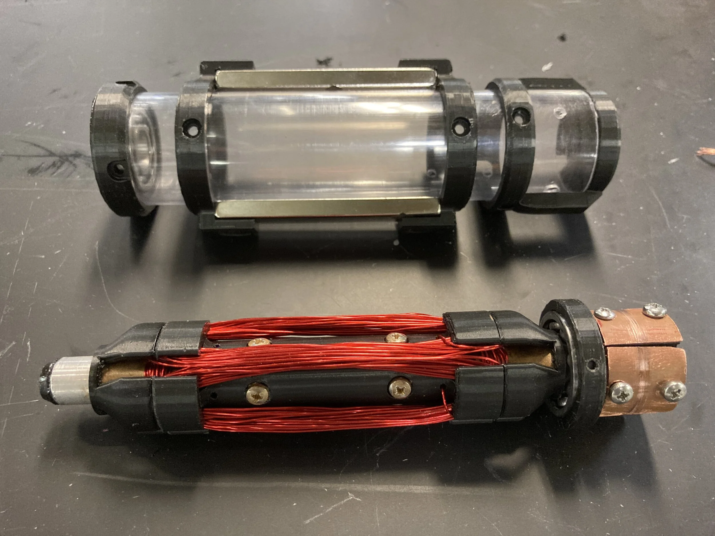
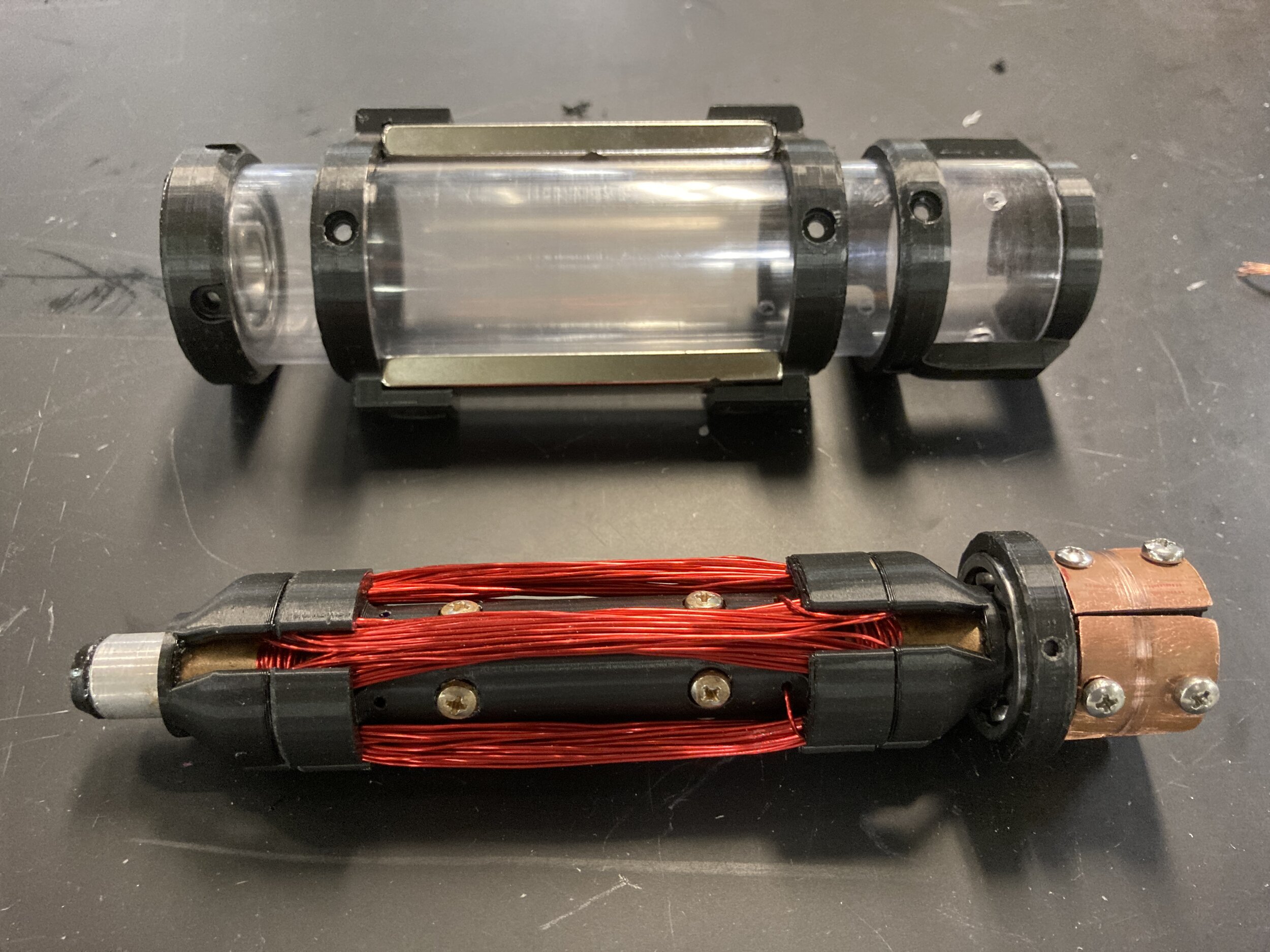
Side-by-side of housing and internals! *Sigh*, it all just looks so clean I can’t even

Connecting it to power and hearing it scream was also very exciting!
You can’t hear a gif, but don’t worry there are videos later!

Another quality-of-life feature I threw in last minute, was the addition of a power socket! (the rectangular red plug on the left)
A lot of other MECH 488 motors just had exposed wires hanging off of them to be alligator clipped to, so I figured this would be a bit more elegant.

Demonstration of me plugging in a power cord!

Another demonstration of the magnet holder, and how different versions can be ‘hot-swapped’ out to vary repulsive force and therefore motor torque!
I’m still impressed at those two little neodymium magnets being able to secure such a large mass!
Here is our final powered demonstration, for final graded submission and in which I subject my teammate to slight verbal abuse
I apologize 😔
And here is our walkthrough / explanation video, all shot and masterfully edited by our Hope!

Final side-by-side comparisons of the motor against its original CAD models! I’d say we did very well! This was a fun and chill project to do with some school friends in our final semester :)
Thanks for reading!