
Building a 3-speed gearbox
In Fall 2018, I enrolled in a workshop class at Rice, and one of our assignments was to implement one of the mechanisms from 507 Mechanical Movements. Rather than follow the assignment guidelines, I decided to do my own thing - as usual.
I had just recently learned to how to use a manual transmission in my friend Jon’s Jeep, and so wanted to build a gearbox!
I ran the idea by the instructor, and the conversation went something like this:
Him: “No, it’s too complicated”
Me: “Too bad, I don’t care”
- and then I ran off. I did the entire project outside of class hours so he wouldn’t keep bothering me.
Being told that it was too much for me to handle made me extremely determined to prove myself.
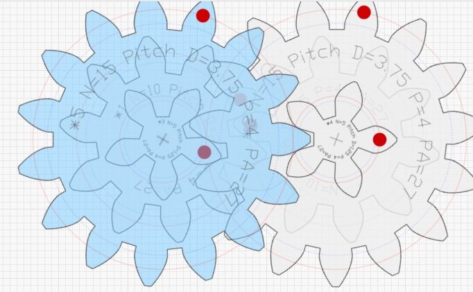
I started by finding combinations of compound gears that could spin together, by messing around on geargenerator.com.
I was looking for gears that shared the same distance between their axes, so I could stack mount them coaxially.

An early CAD model – the orange gear on the left was originally supposed to interface with the motor I was going to use- more on that later. (I was still a TinkerCAD scrub at this point)
The gears are stacked 3 high because I wanted more contact area between gears to have more margin of error while shifting – this way, the gears wouldn’t have to be perfectly in line to still transmit torque.
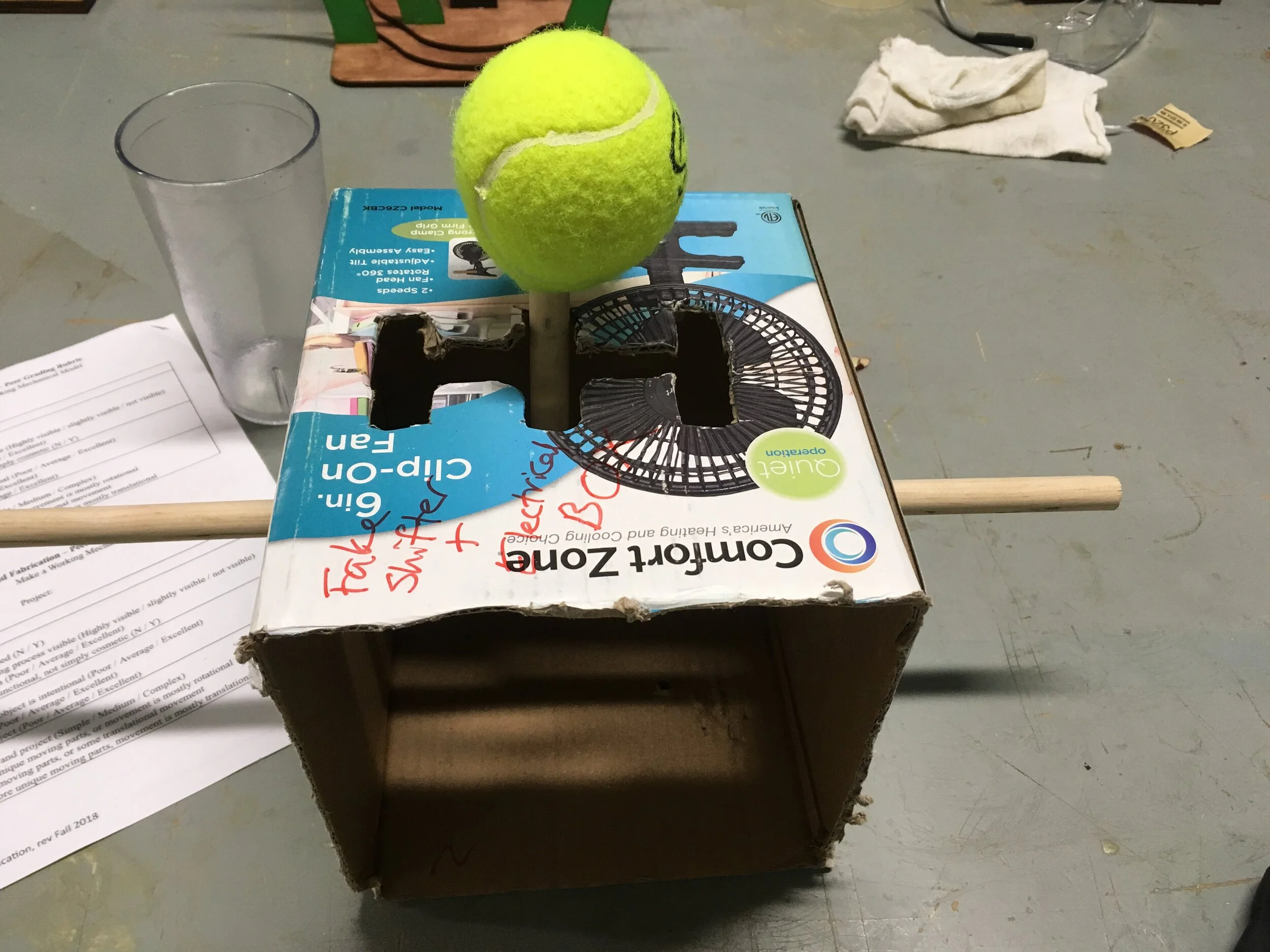
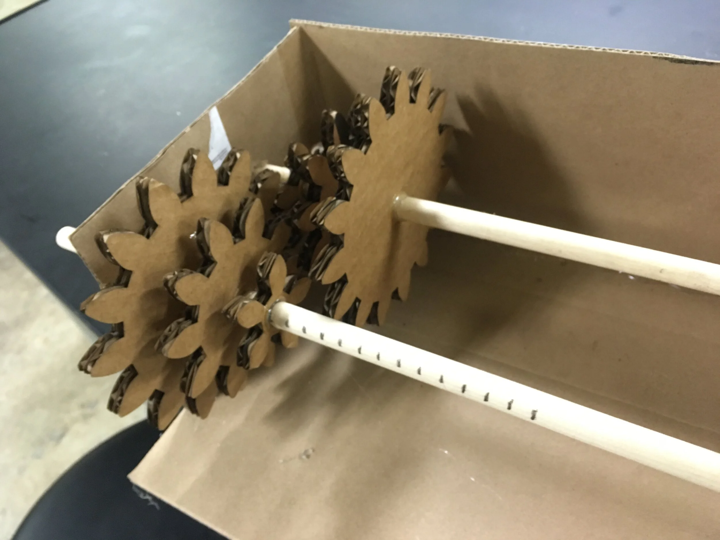
Some low-fi prototypes for the shifter assembly and the gear stacks! The axle on the right picture is marked at 1 cm increments in an attempt to find the best gear spacing. The spacing shown would have given me only 3 cm of shifting throw, so in my final gearbox I spaced the gears out more while retaining their distance ratio for clean shifting.
It was also here that I realized how boring and gross wooden gears would be. Not to mention looking at previous [class name redacted] projects and being unimpressed with how stiff and jam-prone wooden gears were. I decided to cut my gears out of something with a lower friction coefficient: acrylic.
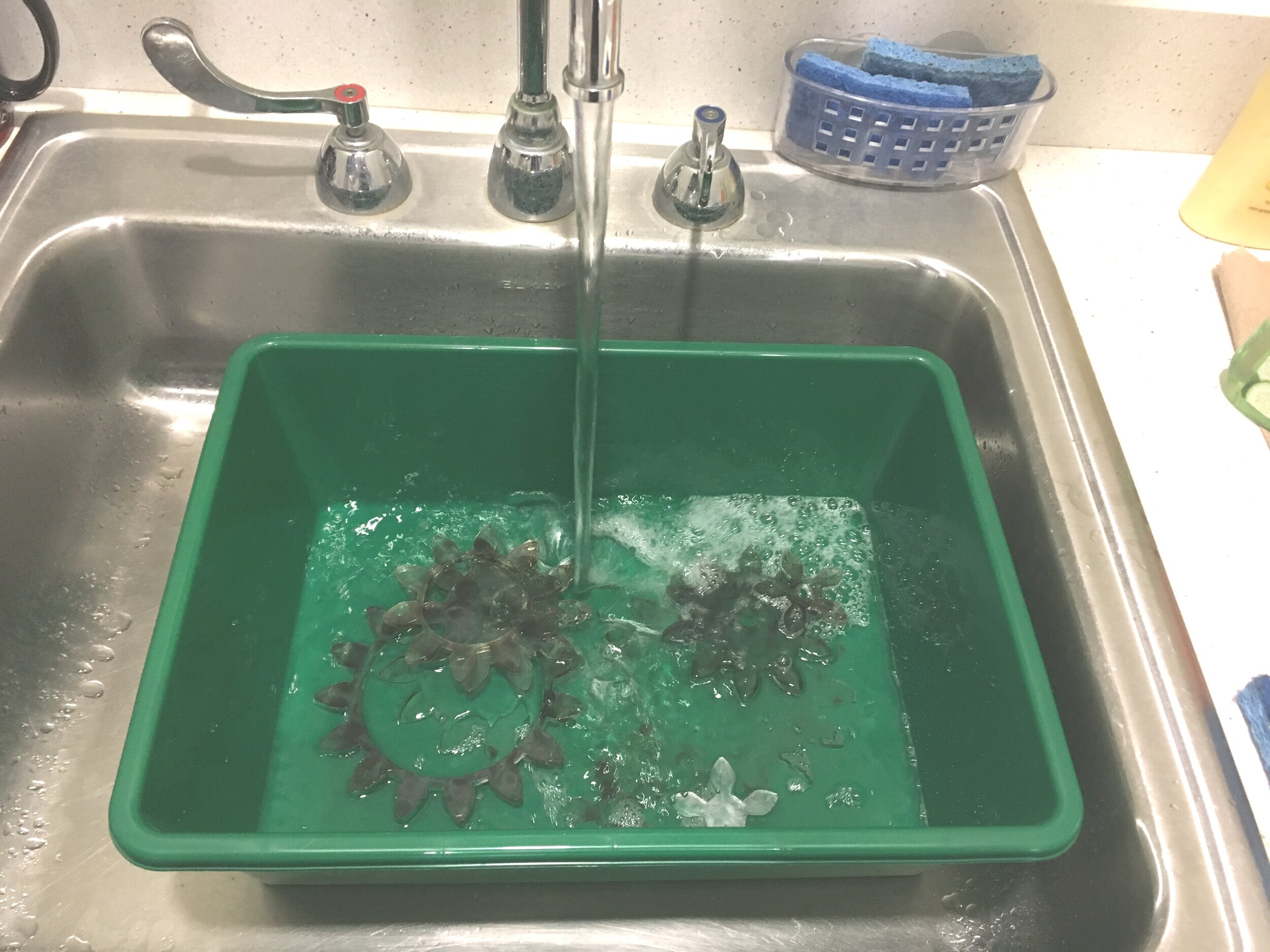
My acrylic gears came out of the laser cutter a little burned, so here I am attempting to wash them clean.

Naturally with clear acrylic gears, came the idea of lighting them from inside. Here I am testing various LEDs to find their forward voltages.
The idea was to go from green to yellow to red with higher and higher gear ratios (like redlining a car tachometer!) It turned out to be a pain to try and find a voltage that would satisfy all three colors, but I found a solution – more on that later.

I used makeabox.io to create nesting boxes as the main body of my gearbox. I wanted multi-layered walls because I was going to be mounting some heavy-duty stuff to them, and didn’t want them to fail. The holes in the sides are for my axle bearings.

I had the idea of using metal rod as my axle, instead of wood. I wanted to try having the rod act as both torque transfer and electrical conductor (~wire) for my embedded LEDs.
Here I am attempting to solder a zinc-lead solder onto a stainless steel rod. For those unaware: it doesn’t work. I came up with another solution – covered later.

This was the huge 12v motor I planned on using. It was going to be mounted onto the face of a wall, before I realized…

The bolt head would run into the motor’s gear and prevent it from spinning.
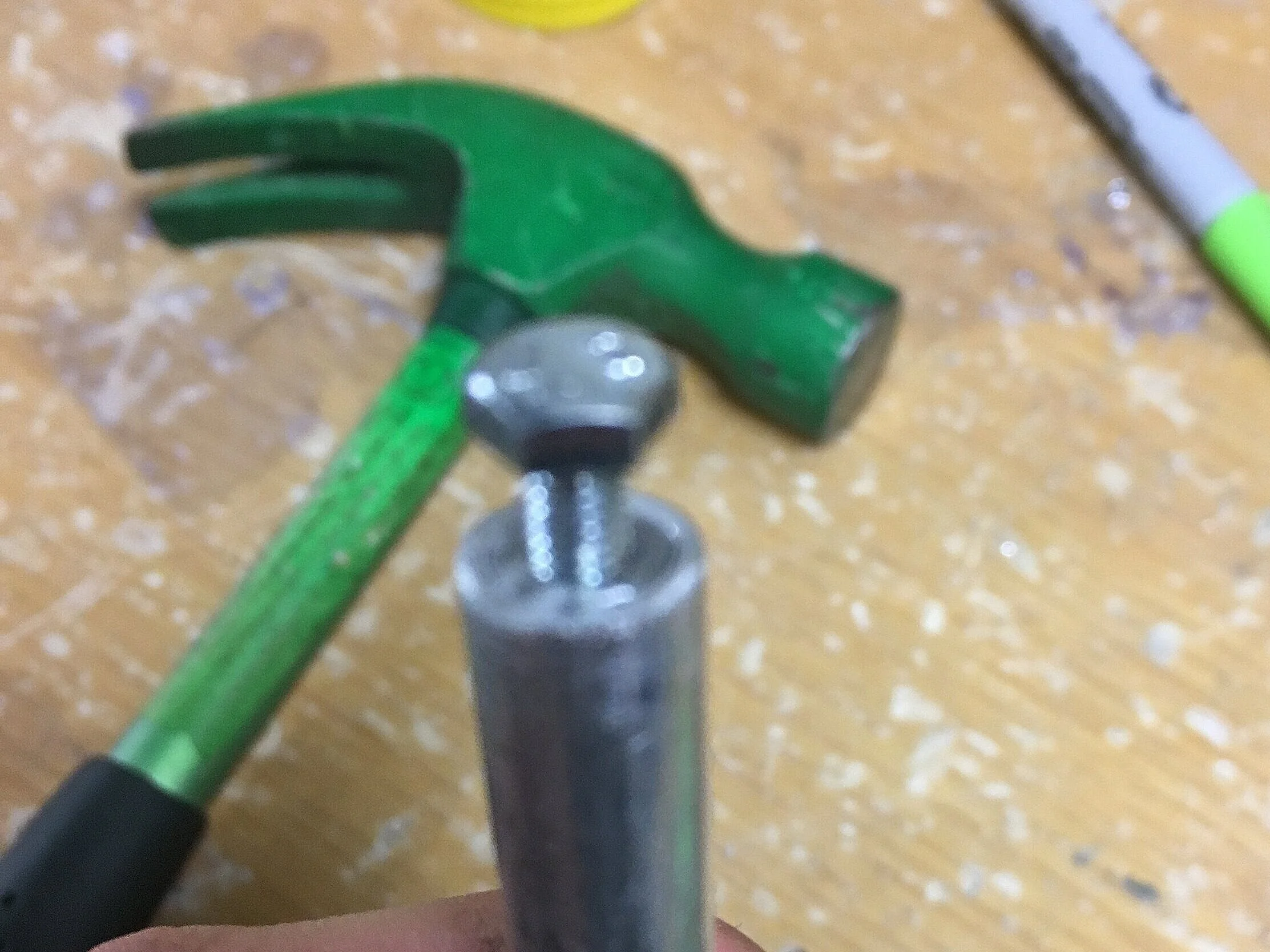
Being the super genius that I am, I came up with a pretty cool (in my opinion haha) workaround.

I drilled into a dowel so that a nail could fit into it, then shaved down the radius so it would fit in the motor mount holes.

The nail would penetrate through from one side of the wall, through the dowel, which bridged the gap between the diameter of the nail and inner diameter of the motor mount points.
This could easily have been 3D printed but nooo, the instructor wouldn’t let us. >:(

The flat head of the nail meant that the motor’s gear could now rotate over the fastener. Nice!
Too bad I ended up nixing the motor in favor of a hand crank, meaning all this work ended up wasted.

Test-gluing the gears together with hot glue. It’s hard to tell from the picture, but the two outer layers are solid gears, while the middle gear is a hollow ring, creating a cavity inside which I planned on sticking LEDs.
Gear mesh test - success!
Validated my gear ratios and axle spacing.

Disaster strikes – turns out, the motor was so torquey that with even the smallest jam, the motor kept on driving the gear and cracked off one of its teeth.
In addition, the square taper I put in the gear’s center bore also got completely torqued circular. No wood or acrylic would be able to stand up to this motor, at 12 volts at least.

I tried experimenting running the motor at various different voltages (11.1, 7.4, and 3.7, from left to right), but even then the motor was too fast.
I realized there wouldn’t be a long enough time window for anyone to get a full gear shift in. The motor would shred everything.

The red 18650 cells from the last photo were actually from a deconstruction activity we did! I disassembled a heart monitor device and held onto its batteries.

In a fit of rage, I destroyed my other gears.

Just kidding. This was an extra gear I had that I broke into pieces to test acrylic glue adhesion.

Comparison shot between a. fresh out of the laser cutter, b. washed, and c. frosted (by sanding)

My sanding setup: I clamped a strip of sandpaper to the table and used 400 and 1000 grit to painstakingly sand all 18 gears I had.
But when my remembered my workshop had a sandblaster, I realized I wasn’t as much of a super genius as I thought.

Planning my LED layout for inside the gears!

LED leads soldered in parallel. I am good at soldering.

One of my gears, LED embed/install complete.

It’s L I T

The solution I mentioned earlier for having different-colored-lighted gears was to have just one type of white LED (one uniform voltage requirement – I wouldn’t be burning LEDs of one color while under-powering another) and have the gears themselves be colored.
These are Testors enamel paint. The instructor misunderstood my part requisition and got these random ones. I initially wanted Tamiya’s translucent paint. These worked, but nowhere as well as the Tamiya plastic dyes would have >:(

The LEDs were bright enough to shine through the non-translucent paint.
Tamiya still would have been better tho…

I needed some way to attach the gears to the axles and transmit torque. My initial thought was to use shaft collars, but the makerspace didn’t have any that fit, and I didn’t think I’d have time to order any.
So I lathed some ‘top hat’ pieces out of aluminum stock.

Here are all my top hat buddies!
The brim of the top hat was to sit on the gear face and have a bolt run through it and the gear.
So I drilled. a. hole.

However, the head of the bolt was still too close to the vertical part of the ‘hat’ for an M3 screw.
I dremeled out a channel to make room for the bolt…

And now everything fit!

Top Hat installed, top…
… and bottom views

Because the n=15 gear (the largest one) one was so heavy, I added 2 through-gear bolts to it, as well as cutting the hat itself shorter.
(That’s a strategy I’ve been using a lot in builds - when machining a part to fit in an indeterminate space, always leave extra material! You can cut away material but it’s difficult to add more on)

Hats installed on all 6 gears (6th one is unfortunately camera shy)

Finalizing my laser cut box and bearing placement!
With some added decoration!!

Test fitting axle and gear placement.
The top box was my lo-fi piece from earlier, and the bottom one was the final version.

Marking out gear fitments on the axle.
By this point, the gears had been bolted to the ‘top hats’, but they were free-sliding along the axle still. I figured out the appropriate spacing and prepared to permanently bolt them down.

And according to the gear locations, marking mounting holes for the ‘hats’ as well as entry channels for the wires I decided to run inside the axles.


I dremeled a channel and used a screwdriver and metal fatigue to pry the resulting metal tab out. I later filed the slot smooth.
Metalworking is dope, the material is much more predictable than wood or plastic.


I ground a bolt and nut down to fit into the hollow space between my gears. Since my axles were wired up as (+), the plan was to screw into the axle at each gear to tap into the current. All three gears on each axle would be in parallel, and the two axles would be in parallel too
(TL;DR each LED gets the same 4.5v but shared current).

Screwing the positive wire for the LED harness into the (+) axle

Screw placement in hollow section of gear

Next, I had to run my negative axle lead through the hollow axle. I had all my top hat fittings installed first before threading the wire, as wiring first and screwing second could risk cutting into the wire and causing a short.

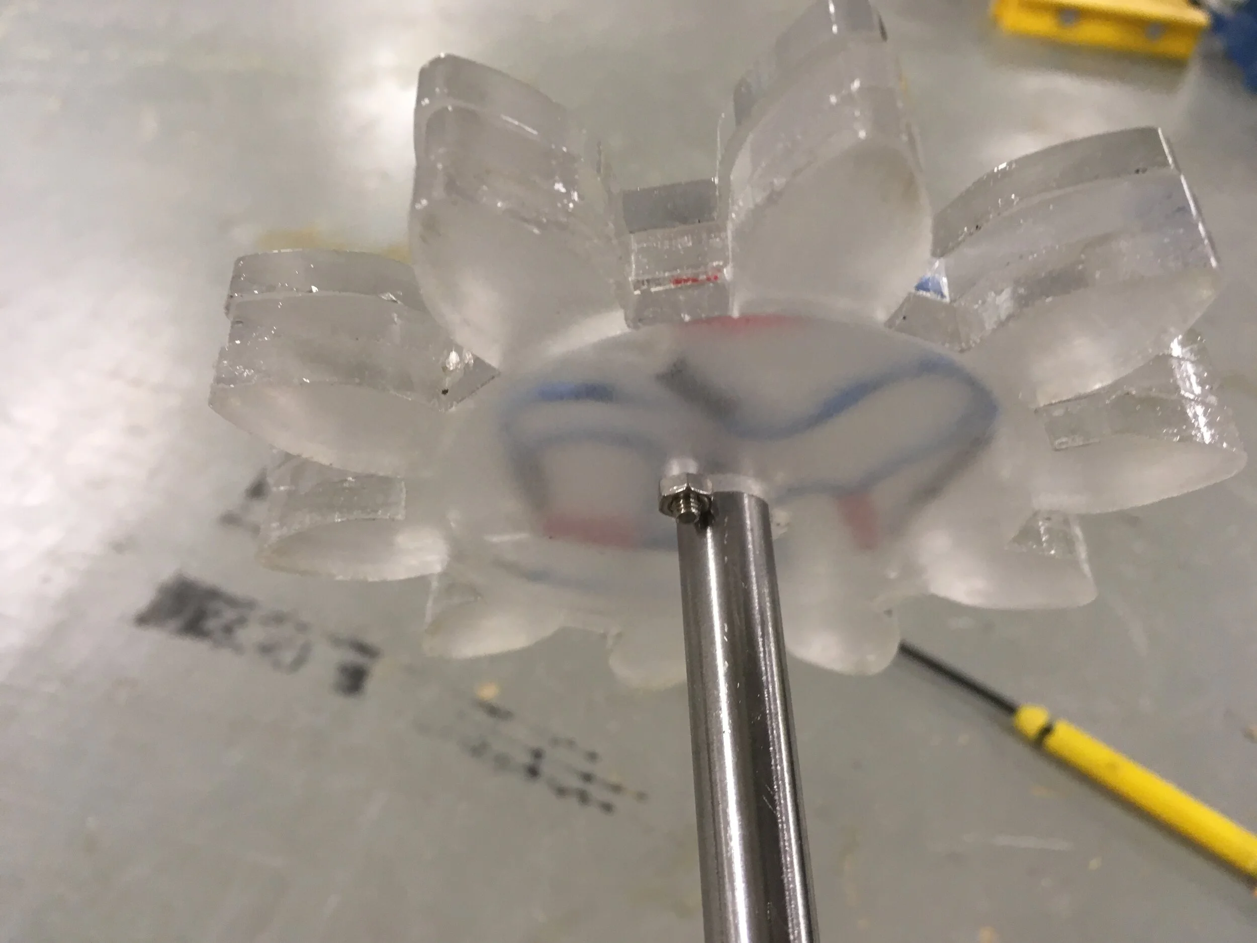
Because the interior of the axle itself was a maze of differently-oriented bolts, I used another clever trick to be able to thread my wire at all. I soldered an extremely thin, single-stranded wire (the blue one in the left picture) to my actual black wire, threaded the thin wire through easily, and used that to tug the black wire through.
(I got the idea from a Greek myth - Daedalus threads a seashell)

Note the yellow alligator clip attached directly to the axle.
Shaft itself conducts current - something I’ve almost never seen done in projects / industry!

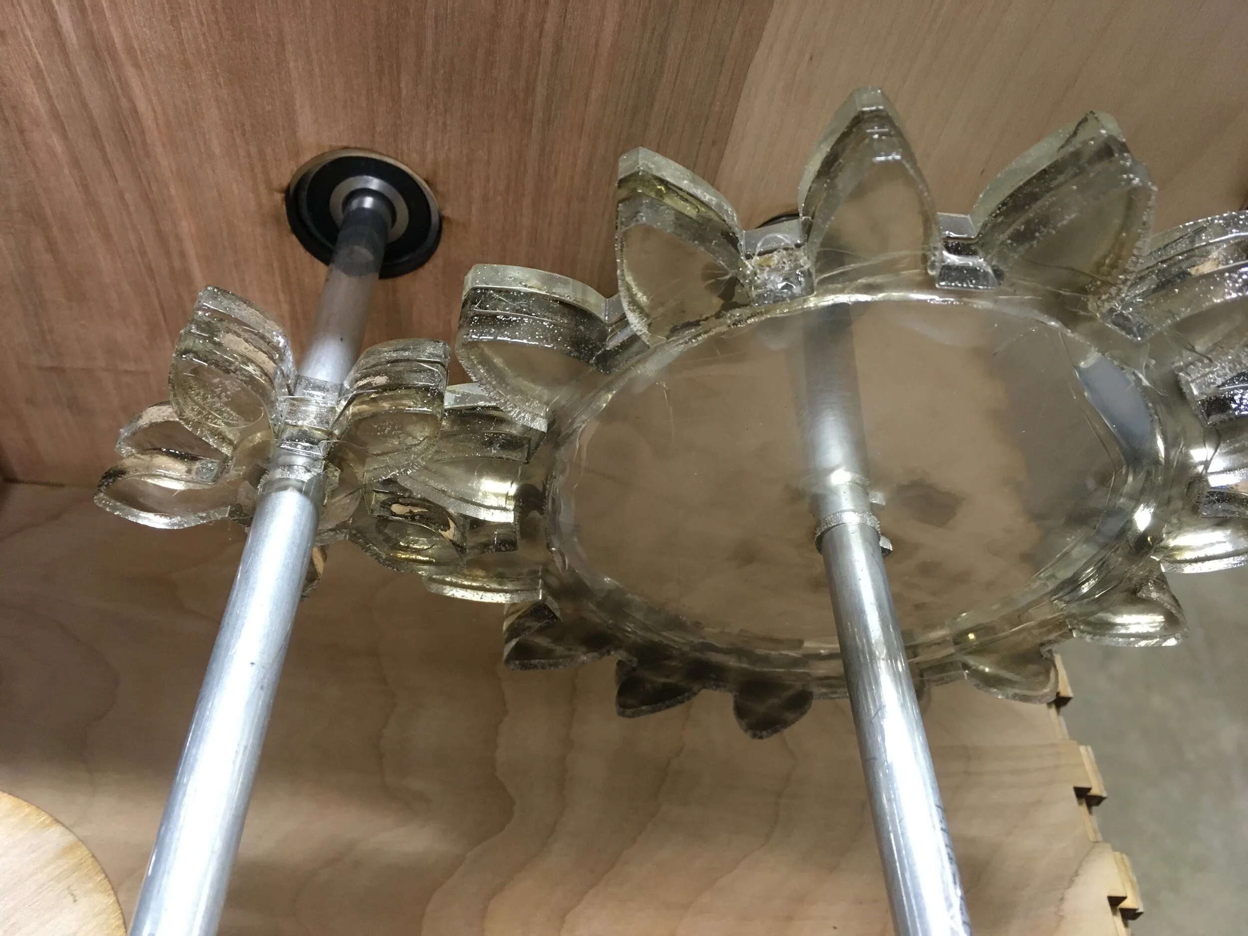
YEAAAAHHHHHH!!!! Like a Christmas tree!
Seriously, this thing looks so clean without external wires between the gears!

Because I was going to run power through the axle and bearings, even though most of my axle was wired (+), there needed to be at least a small section of it wired (-) to interface with the (-) bearing.
To do this and to have everything still coaxial, I needed a nonconductive spacer, which I lathed out of plastic.
Could easily have 3D printed such a piece - lathe was absolute overkill for something like this - but again, instructor.

Final shot of my spacer, before being press fit and epoxied into both ends of my axle.

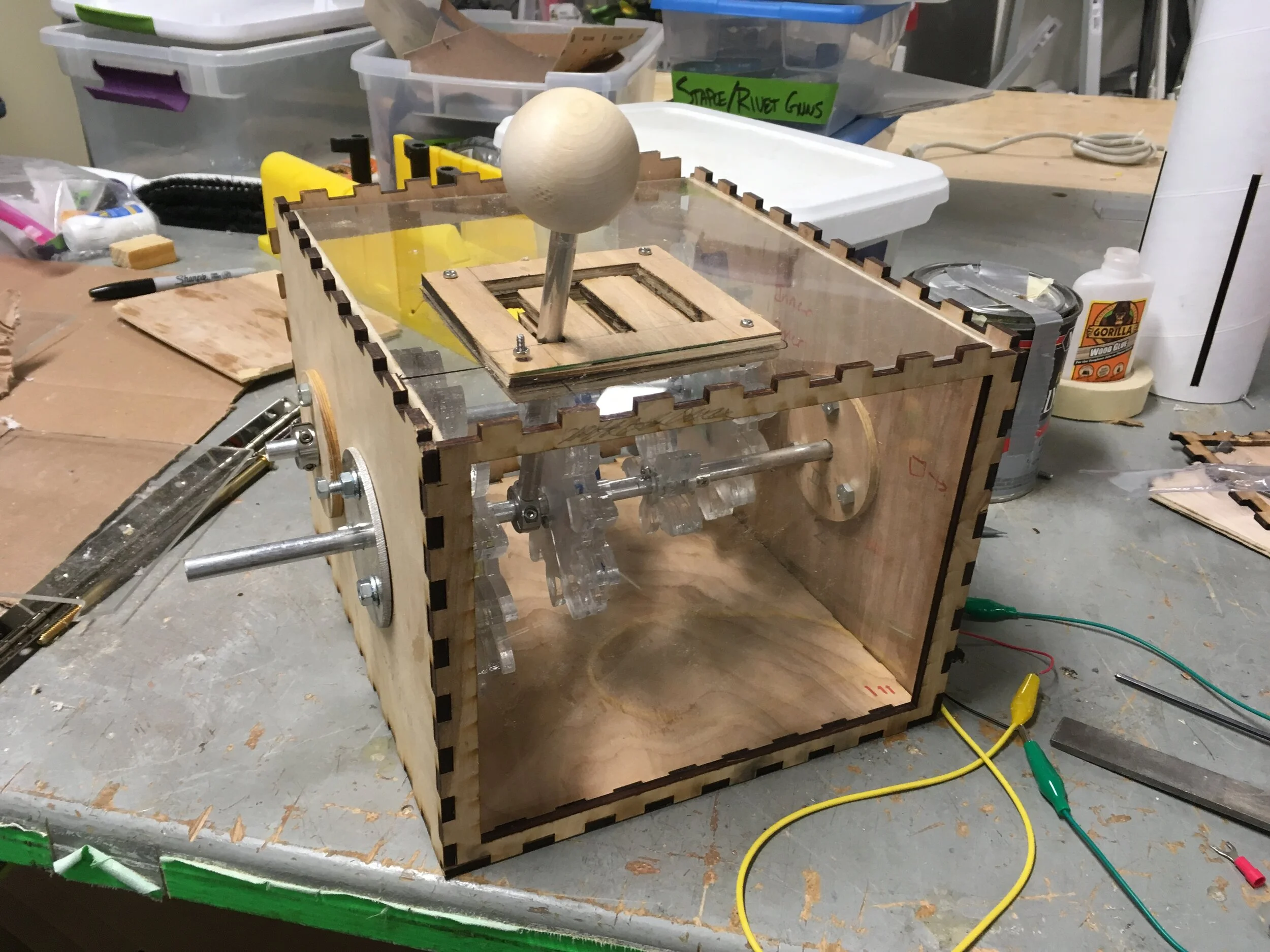
Assembled and powered!

Now onto building the shifter assembly. The plan was to have a shaft collar grabbing a section of axle to slide it up and down to align different gear paths.
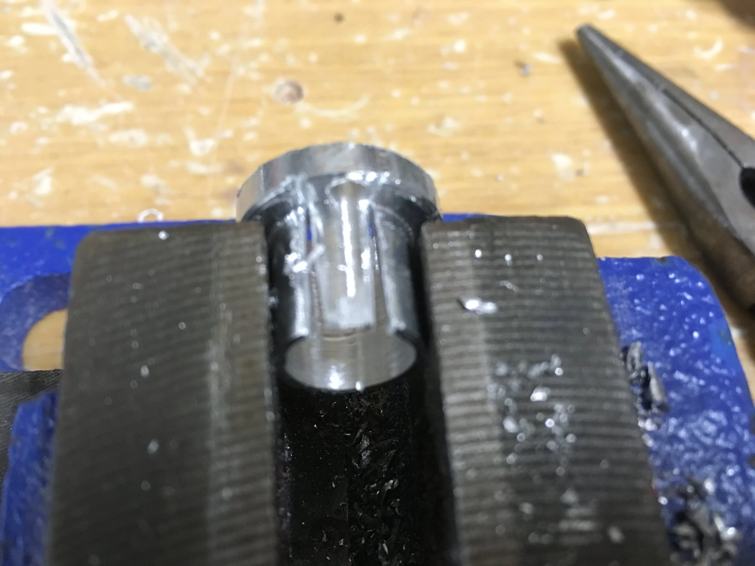
Since the workshop didn’t let me lathe that day, instead I clamped a bearing in a vise, placed the axle into a drill, and made my own lathe.
Improvise, Adapt, Overcome.

Using my makeshift lathe, I turned down a section of my axle. This was so the shaft collar could still spin freely radially while being able to control the axle axially.

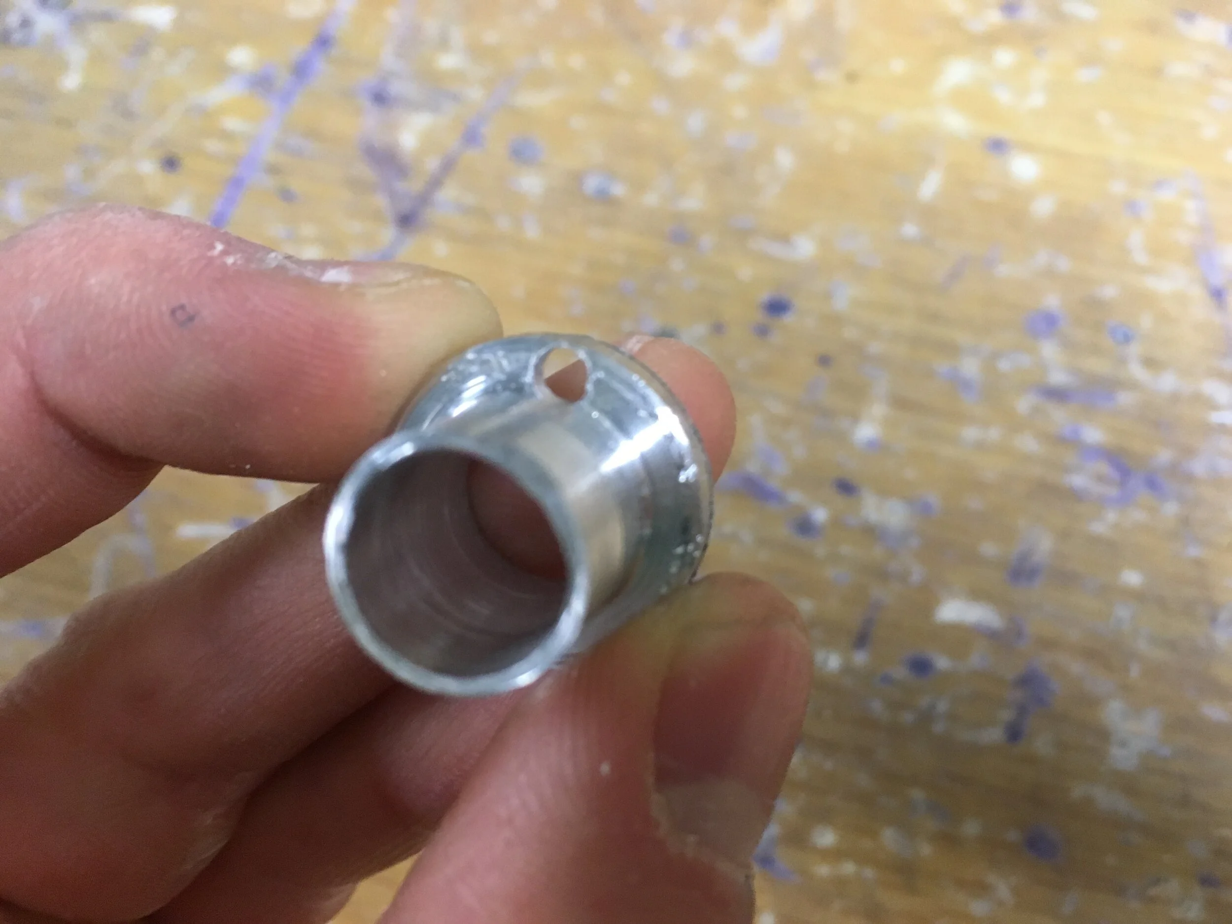
I ground down a nut into a circle and press fitted it into some aluminum hollow shaft (my shifter), effectively making a female threaded rod.
A bolt was to go through and attach my shifter shaft to the shaft collar.

I drilled out a hole in the inside face of the shaft collar, large enough for the head of a bolt to fit completely flush within it with the threads facing outward.

Exploded view of shifter assembly

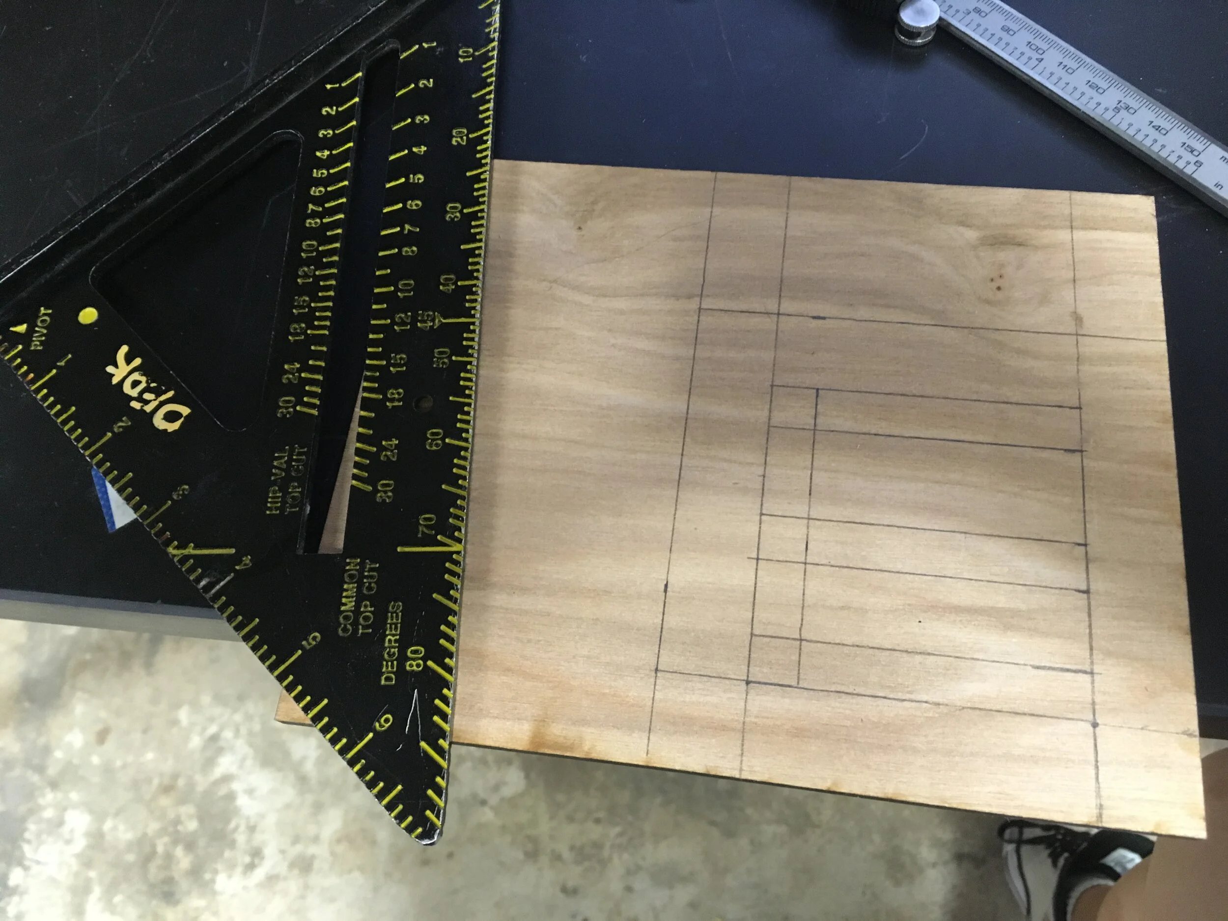
Shift lever installed - Now I could see where it landed and plan my shifter gate paths accordingly.

I did this with a piece of cardboard I cut, to get the dimensions out of after everything fit up nicely.

Since the laser cutter was broken and I couldn’t afford to wait, I cut my acrylic with a dremel.

I got my dimensions from my cardboard template and mapped it out on acrylic.

Utter garbage. Precision cutting with a dremel on acrylic is hard.

Also, since the acrylic was only 3mm thick, the lever could angle within it and misalign the gears. I realized I needed not only tighter slots, but a thicker vertical dimension, so my shaft would wobble less.
I salvaged the situation by cutting two more shifter gates out of wood…

… to mount above and below the acrylic panel layer.

Assembled!

To run power to my bearings, I initially wanted to screw directly into the bearings, but trying to drill press into one didn’t work, so…
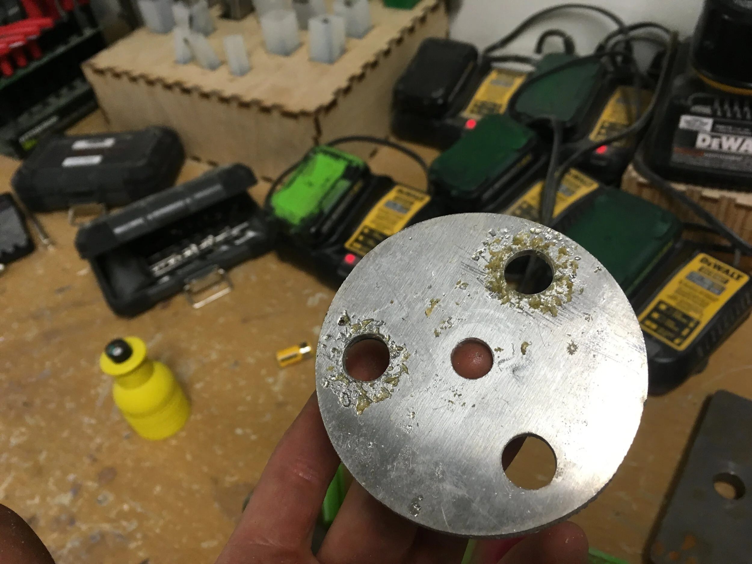
Enter my plasma cut piece (shown after having its holes cleaned up with a drill press) The plan was to run power to this disc, which would contact the bearing, which would contact the axle, ensuring continuity in my circuit.
For the other three bearings, though, I decided to use washers (not sure why). To do this, I would have to build washer/bearing housings.

Because the laser cutter was still down…
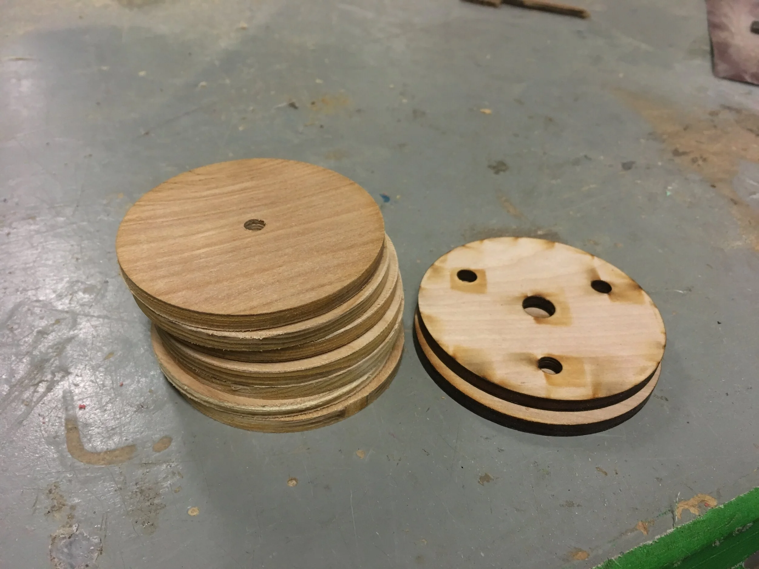
I used a hole saw to cut discs out of plywood!

Drilled out mounting holes

And using those same holes in a centering jig…

Used a Forstner bit to…

Cut recesses for the electrical washers to sit flush in!

Painting! I had the gears powered on throughout, in case paint seeped in and coated my electrical connections. This way, I could immediately recognize if it had happened, and clean the contamination before the paint cured.

All painted up!

I decided at 4AM that I wanted the top of my box to be hinged.
And done!
In this project, I think I attempted a really ambitious design, and came up with many creative and unconventional solutions to my problems (threading cable, rotary current transmission, makeshift lathe, etc.). Certainly more complex than the ‘safe’ one the instructor wanted me to do.
Though I took some extra time, I achieved all the original criteria I wanted to meet, and am glad this project is finally over.
(There is more to this build, but I will not be sharing it here. That is why the writeup ends abruptly. If you’re curious, feel free to contact me)