Lightsaber

In Star Wars, a lightsaber is a blade of frozen plasma, focused from a “Force-sensitive” crystal, and contained in a magnetic field. Since we are not even remotely close to this level of engineering, the best we can do is to make cheap facsimiles to amuse ourselves.
This page covers the creative process in creating my own custom lightsabers, starting from primitive models I built in middle school, to the Lipo-powered, magnetically-activated versions I am creating now (Seriously, please read until the end. It’s worth it, I promise). I am aware of many of the higher-quality builds out there, but these were never meant to compete with them.
My lightsabers are first and foremost designed to be used, and not just sit in a display case. They are playthings, to carry out the imaginations of a middle school Brian. I had no use for a prop that I couldn’t swing around and beat my brothers with.
As such, the design sacrifices some things, such as sound effects and metal handles, in exchange for low cost, customization, and durability.
mark i
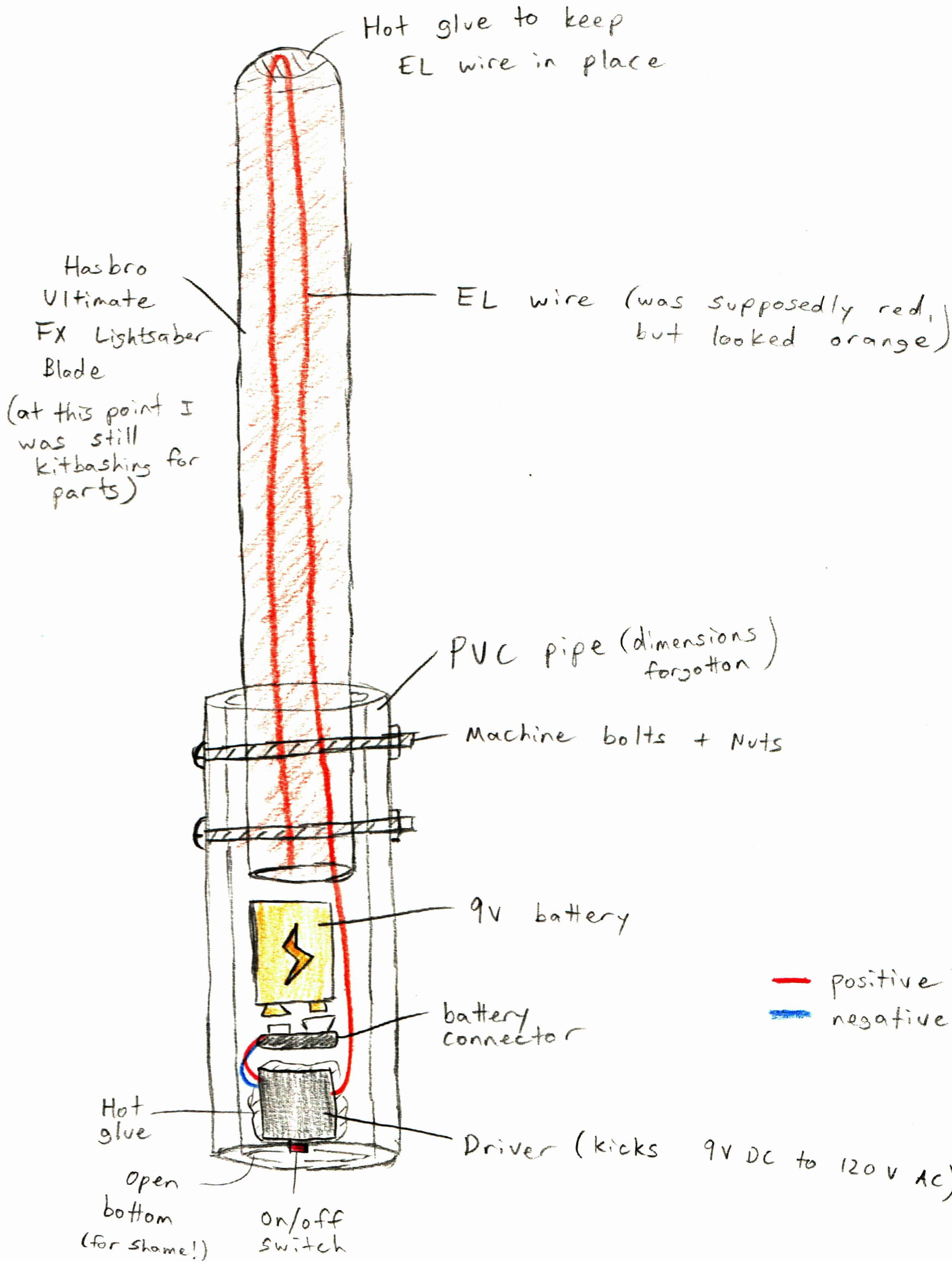
Mark I was my first serious attempt at building a lightsaber. I was in middle school at the time and before, the most I’d ever done was to tape a roll of colored paper over a flashlight (something I’m sure we’ve all tried). I’d recently heard of electroluminescent (EL) wire, and wanted to use it in my lightsaber. EL wire consists of an extremely thin strand of wire coated in phosphor and clear protective insulation. When alternating current (AC) is applied, the electrons excite the phosphor and make the wire glow. Sounds cool, right? It is.

So I bought up a big spool of it, along with the DC to AC driver and other parts, and threw the thing together. It wasn’t pretty. It was really dim, and my handiwork skills weren’t that good then. However, I learned a lot and applied it to my next build, the Mark II.
Mark II

(what almost became) Mk ii
This was a conceptual sketch of a lightsaber I drew in seventh grade, when my imagination still far exceeded my practical building skills. What’s interesting is that even though I had no hands-on experience at the time, this would almost be the exact Mk. II design, save for one detail: battery placement. I assumed that a 9V battery would fit into 1″ PVC pipe, but I was wrong. Hence the “almost”.

Prior to the development of Mach II, I spent a great deal of time looking for a better alternative than EL wire. Some online forums suggested LED strips, but your typical LED strip only shines in one direction, and the strip itself blocks a lot of light. Obviously undesirable when designing a lightsaber.

Prior to the development of Mach II, I spent a great deal of time looking for a better alternative than EL wire. Some online forums suggested LED strips, but your typical LED strip only shines in one direction, and the strip itself blocks a lot of light. Obviously undesirable when designing a lightsaber.

I found the below image online, with LED leads soldered directly to one another to allow light to disperse in all directions, but this design seemed too fragile to me, especially considering all the beating it was going to take.
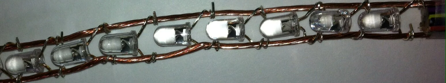
I modified this design by wrapping and soldering the LEDs onto 16 gauge wire instead, for both structural integrity and conductivity.

I chose to use thin polycarbonate tubing for the blade instead of kitbashing the blades from existing storebought toys, as I’d done before. Polycarbonate is much tougher (in both impact-resistance and tensile strength) than most other clear plastics, so it was ideal for something that would be used to hit things.


In addition, I had used a thicker PVC as the Mark I hilt, so I didn’t run into the problem of a 9V battery not fitting inside. In Mark II, I switched to a thinner 1″ pipe. However, even though a 9V battery is smaller than the pipe’s 1.315” outer diameter, it was just barely too large for the 1” inner diameter. I opted to cut into the walls to make some extra space, creating Mk. II’s characteristic “slot and prongs” look. I cut the slots slightly smaller than the width of the 9V, so when the battery was inserted, it forced the prongs apart, forming a tight friction fit with the endcap.

Here is my friend and happy MK II ‘customer’, Jacob! We ran a workshop for East Lyme High School’s Maker Club in 2015, where we ‘mass-produced’ MK II kits for anyone that wanted one, and walked them through assembling their own. Good times!
Mark iii

NOT the actual MK III design
I found another sketch from my middle-school notebooks that featured three AA batteries instead of a 9V. What’s interesting was at the time of drawing, I didn’t have any electronics knowledge, and couldn’t have known that a couple of AA’s would be better than a 9V and resistor. It still has me confused me to this day.
I think I kept wanting to use 9V batteries then because it was what the original EL power converter used, but in hindsight it makes so much more sense to use a the correct LED operating voltage (~3-4.5 usually) rather than stepping down from 9V)

Mark III ended up being a nightmare to visualize and design. The circuit itself was dead simple, with just an LED strip, switch, and battery pack, but the physical design was something else entirely (at least at that point in my building career)
10/18/2020 Edit: I just thought to point out that I had no CAD or 3D modelling experience at this point in my training. I’m really impressed with what little 17-y/o Brian was able to visualize and design back then.

It featured 4 different-sized tubes interlocked in a friction-fit 3D puzzle. An endcap slid off to reveal a tube-style battery ‘magazine’ (like a tube-fed shotgun), and the main body had a inlet cut in it to make disassembly possible. I didn’t know any CAD software then, either, so I basically hit rocks together to make fire, so to speak.

Just to give you an idea: Installing the switch alone involved: cutting a slot in the blade, cutting a hole in the outer shell, prewiring the switch with extra wire, then snaking them through the hole, slot, and main tube, and pulling everything through using the extra length, then soldering to the battery plug and one end of the LED strip. Then I flooded everything in hot glue and prayed none of my exposed contacts touched each other. (At the time I didn’t know heat shrink existed)

Even the battery contact face was a repurposed wick holder from a tealight candle.
This is the level of homemade we’re talking.

Early mockup of the telescoping/nested tube design

Prototype MK III model

A completed MK III model
mark iii: SPecial edition
I designed Mark III during senior year of high school, and guess what else happens during senior year of high school? College apps, that’s what.
It just so happened that my English and AP US History teachers were about to have their third child. My English teacher had helped me out a TON with my college essay, and my APUSH teacher was writing my letter of recommendation. It was around Christmastime and their baby was right around the corner, so I wanted to build a trio of sabers as a present that tripled as a thank you, Christmas present, and baby shower thing.
I always do better work when I’m building for someone else, instead of myself. Maybe because it’s because I feel like I can’t give out subpar work, or maybe the prideful part of me wants to show off a bit. Either way, I knew I had to make these special.

Marking cut lines in Sharpie

Mockup after hand carving + sanding

Painted! (by hand!)
I painstakingly marked, hand-carved, and painted three hilts. Because my APUSH teacher was about the most patriotic man I’d ever met, I wired the blades with red, white, and blue LEDs.

I think he liked them

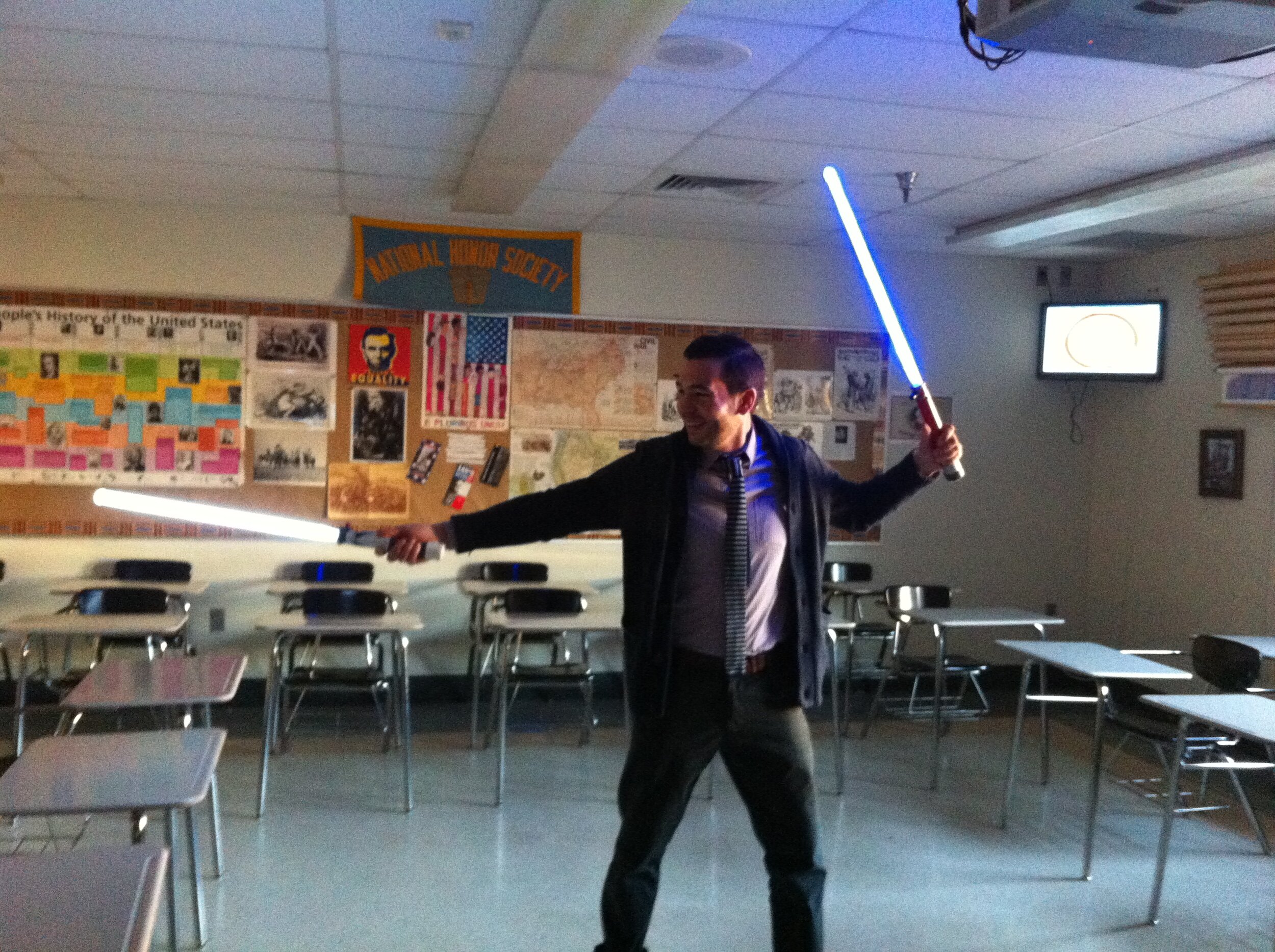
Here is me too - go Dark Side!
mark iv

See? Things I build for personal use stay jank and unpainted. I save my best work for others.

Mark IV was a quick and dirty summer build after my first year at college. It was largely the same as Mark III, but I modified it to take AAA’s for a more compact hilt, and implemented a different side-loading battery setup.
This shorter hilt limited MK IV to single-hand combat only, but that was okay because there is a shield for the left hand in the works!

At this point, I hadn’t learned coding to program a microprocessor yet, so that meant no controlling RGB LEDs. I worked around that by remembering those flashing/fading rainbow LEDs found in cheap dollar store toys, and ordering a bunch from China.
Due to QC tolerances (probably), the blade starts off a singular color, then differences in individual bulb resistances cascade, and the blade dissolves into a Technicolor mess.
After all, why use a Jedi mind trick when you can just give your opponent a seizure?
There’s not much else to Mark IV, like I said. It was mainly to finally build an up-to-date saber for myself after having gifted everything else away to friends.
Mark v
I built Mark V as part of a COLL 198: Hands-On Electronics in college. Some small things I changed up were:
using a single 3.7 v 18650 LiPo cell as the power source, instead of AAA’s
3D-printed an end plug (with recharge port!) instead of bulky PVC endcap
using an ultra-dense LED strand (more consistent glow)
simplified interior design (lost some of the elegance of Mark III but was sooo much easier to build)

It’s hard to tell in the photo, but these are the same patterns I carved into the MK III: Special Edition’s! With the silver accenting swapped out for edgy, bloody red!!!1! (JK I only had these paint colors on hand).
IN ADDITION – I changed one more key thing that really set Mark V apart from the rest. With my now-educated a** knowing power electronics, I added in a reed switch and a protective MOSFET circuit as my activator. No more physical switch, which meant…

That’s right. MAGNETS!! (Those are magnets taped to my palm).
Mark VI activates whenever a magnet moves into close enough proximity to it, and trips the reed switch.
Like the Force… well, kind of.

It was such a great party trick to pass it around, have everyone try to activate it, then pull a Thor on them with a hidden magnet.
Fun times were had on Advisor Crawl 1.0 bamboozling friends

And thanks to the 70-odd LEDs I crammed into the mere 2 feet of blade, this thing is crazy bright. It even left a little corona effect in the camera :)
Mark VI? (more to come)

Don’t think for a second that I’m done. Some things I want to add to future versions are:
individually addressed LEDs for scrolling/flashing effects
RGB-programmable LEDs, so I can change blade colors at will
A soundcard with one set of lightsaber-accurate sounds, and another set with joke sounds
Accelerometer to measure speed and impact of hits
Arduino + Bluetooth module to link to my phone
DUAL BLADES