
Superior Assault gauntlet Apparatus (SAGA)

In this inaugural edition of Brian Builds, I create SAGA - a forearm-mounted, tactical (😳) gauntlet with Nerf autocannon and actuating, lighted bayonet —
And in doing so, birthed an entire project lineage and inspired the existence of this very website!

As a lifelong Megaman.EXE fan, I’ve always been drawn to the gauntlet arm cannon aesthetic. Just being able to point your hand and pew pew has always been a dream of mine.
As a kid, I had to stick my forearm into a cardboard shipping tube and play make-believe, but now knowing much more about design and fabrication, I decided to build something better.

I named it the Superior Assault Gauntlet Apparatus, or S.A.G.A. for short. I tried to make it sound cool, but also stand as an acronym for something, like GUNDAM (Generation Unrestricted Network Drive Assault Module).
This is the synthesis of my all my engineering skill and experience so far, and I’m really proud of how it came out. This project involves gear drives, programming, electronic circuitry, a TON of 3D visualization and modelling, and around 200 hours of work.

Overview
I’ve organized this writeup into the gauntlet subsystems, and tried to arrange them in somewhat chronological order:
Chassis, Part 1 – preliminary frame construction
Mode: SHOOT - Magazine - reverse engineered magazine process
Mode: SHOOT - Autocannon – firing mechanism development
Chassis, Part 2 – frame/body construction
Mode: SLASH – actuating blade development
Control Systems – electronic systems management
Assembly – Oh yeah, it’s all coming together
Extras – prototype display, sketch gallery
Enjoy the build!
Chassis, Part 1


(1) I started by making a cardboard template to get rough dimensions of my arm. One of the main challenges of this build was that I was essentially building on the inside of a closed tube, which is very difficult compared to mounting things onto a flat chassis or other open frame.
(2) The template ended up fitting well with a 93mm diameter hole, positioned 240mm from my wrist.
I added an octagonal border to the outside of the circle to give myself flat outside surfaces to easily mount attachments onto.
(3) My first and second cardboard models. I realized the first one would be too small to house wires and parts inside, so I created a bigger one (right). The slot on the bigger model was to fit the autocannon magazine.

Test fit the CAD (Cardboard Aided Design 😎) model on my forearm!

I built some octagons in Solidworks, then tried a 3D-printed mockup to test the fit.
I initially planned on having the arm hole be 93 mm along the entire gauntlet length, so the only way to secure it would be too have it clamped very tightly around my flexor and extensor muscle bellies. As you can imagine, this was very uncomfortable, and left a lot of wiggle room by my wrist.
Quick mockup with magazine included for visualization.

Eventually, I thought of a better way to secure the gauntlet around my wrist.
I would use a two-piece cuff that would open to stick my hand through, then lock closed around my wrist after my hand had cleared the opening.
(09/23/2021 Edit: More on this later in the Chassis: Part 2 section!)
One idea was to include a spring-loaded handle, that would extend from the blue bottom piece and retract when not in use.
It would have switches placed in appropriate thumb and index finger positions to control the blade and autocannon.
I ended up scrapping this idea, but keep an eye out for it! I’m planning to use it again in SAGA MK III

A taped mockup of the wrist block pieces, and how the control handle would have fitted.
(feat. calluses)

I merged the two rear octagons a single piece and added long M6 bolts as the ‘frame rails’ of the gauntlet. This let the gauntlet tighten around my arm but still be easy to slip on.
(The bolts were salvaged from a Nissan Leaf battery!)
Mode:SHOOT

Next, I wanted my gauntlet to pew pew, and given my background modifying Nerf guns, I decided to use foam Nerf balls and flywheels to achieve this.
(I’d like to point out that Mode: Shoot was completely cribbed from Evangelion 😆)
Magazine Development

This is Nerf’s magazine design for their spherical Rival ammunition.
If I were to design a firing system that could accept these, I would need to make it fit and interface with all the complex contours seen in the orange piece.
I decided that doing so wouldn’t be a good use of my time, and so…


Took some measurements and reverse-engineered my own, simplified version!!
The blue spring-loaded tab/gate on the bottom of the magazine prevents the follower from pushing all the balls out.
It’s angled so that another piece with a complementary angle can depress it to release the ammo.


Said complementary piece. I modelled a magazine well to both fit the mag’s outer perimeter and lock into the magazine’s gate.
The triangular bit on the black magwell piece forces the dart gate down, like so!


Demonstration of magazine releasing on its own, and when pressed into magwell!
Autocannon Development

In order to fire these balls, I opted to use a flywheel system (like a baseball pitching machine).
This particular flywheel cage was one I designed in TinkerCad for another, unrelated application. The flywheels were purchased from the aftermarket company Worker.

Another flywheel cage prototype, this time meant for the gauntlet.
It has a semicircular profile because I was originally planning on using 4″ PVC pipe as the body of the gauntlet. This cage would have fit inside the pipe walls.

Yet another iteration had the cage fused onto one of the earlier-mentioned octagons.
However, this design was not optimized for 3D printing and ended up being scrapped.

Next, I created a really sleek, standalone cage setup, but it didn’t fit the gauntlet’s otherwise bulky, angular aesthetic. The geometries and setup themselves were solid, though, and were incorporated into the next design.

In my next attempt, I simplified the cage geometry, and made it almost Brutalist in style. I even added a miniature ported barrel to the front haha.

I embedded three motors into the cage: two to spin the flywheels, and another to turn a roller (circled in yellow) to control the rate of fire.
Otherwise, the magazine would push all the balls into the flywheels at once, and I would have a shotgun instead of a machine gun. Which would actually be pretty cool…

Firing video! This is with the rate of fire electronically limited to about ~50%, for both ammo conservation and the aesthetic. As in, I wanted boom-boom-boom-boom instead of BRRRRRTT.
Edit 09/23/2021: Some thoughts from a now more-experienced Brian - the motor throttling was done by limiting the voltage provided to it, which dropped the current and torque values as well. This sometimes resulted in jams (not enough torque to feed rounds through with 100% consistency). In the future, I would just choose a motor geared to a lower RPM to achieve the same effect without sacrificing current + torque.
Firing video with sound here!
chassis, part 2

The design evolved to have laser-cut wood slats as the outer skin of the gauntlet, fitting onto the flat faces of the octagons.
Here is an side-by-side of an early mockup and the CAD model at that time.

I split the rear octagon into pieces so I could have half the gauntlet assembled and still reach my hands inside, use tools, and wire things in.
The front wrist block kind of merged with the octagon idea, and has a taper towards the front. The holes littered throughout are for screws, nuts, and wires to pass through.
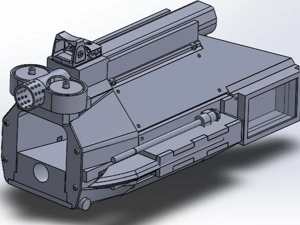
CAD progression triptych!
(1) First, I toyed with where to mount the cannon. I was between top-, outer-, or under-mounting on the forearm, and went with top-mounting it!
(2) Next, I added the blade/bayonet to the model.
Notice the long parallel bolts above and below the blade; those are meant to be the rails it slides on, as well as the conductors to power to LEDs inside of it. This might be clearer in the next image.
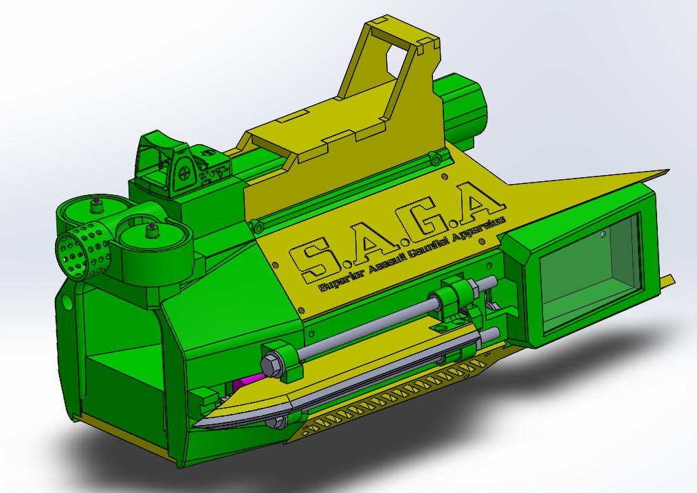
(3) Added all the cosmetic bits. This was really fun!
I added a race car-esque wing, the name plate, a scope, and angled some of the panels to look more aggressive. I also chose to leave the blade exposed. I liked the look better this way.

Once all the CAD was finished, fabrication was easy.
Here is a portion assembled and test fit onto my arm. The front wrist block piece alone (in brown) took 25 hours alone to 3D print.
09/23/2021 Edit: lol at 2019 me thinking 25 hours was a lot

Test fit with all the laser-cut wood panels installed. Looking good!
Part of engineering is knowing when best to use which tools. These panels could easily have been printed too, but this was much quicker and simpler.

Full mockup. I really love how the name plate came out.
I did it by first cutting the panel out of a larger piece of wood, then carefully removing the name panel while keeping the rest of the wood in the laser cutter.
I painted the panel black, then placed it back into the laser cutter, using the other piece of wood as a template to ensure the lettering would be aligned properly.

Painted everything black and gold. This color scheme looks so sick!
I even painted the internal bolts gold too, even though they would never be seen.
I don’t leave any stone unturned in these types of things 😤

2021 Append:
I realized that I never explained the locking cuff mechanism well, so I got included some footage of it here!
A hinged section unlocks and drops down, creating space for my hand to pass through!
The power and bayonet buttons are also hidden on one of these inside faces, as kind of a 2-stage unlock/activation process.

2021 Append:
Here is a closer look at a custom spring-loaded pin I designed to run through the front bulkhead and lock the wrist cuff in place

Tightening down a few last screws!
Self-surgery has always seemed like such a cool trope to me (in fiction, mind you), so in my mind this was similar to that. I felt cool 😅
And yup, those are real bullet casings I’m using as exhaust pipe-like decorations! I had gone shooting for my first (only) time that summer, and saved a bunch for this!

Physical components complete! I even wore my Bakugo shirt for this photo XD
Mode:Slash
After the main body was taken care of, it was time to work on the actuating blade system!
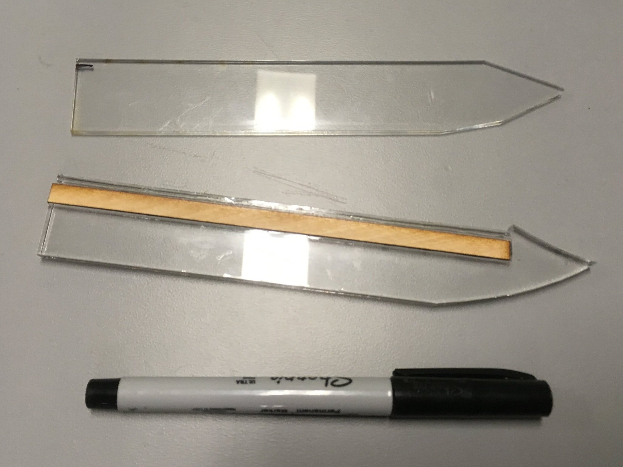
I made my blade out of three layers of laser cut acrylic, sandwiched together and glued into a blade shape.
The middle piece had a long slot cut into it to house the LEDs. During handling and construction, I supported it with a strip of wood to prevent breakage.

To actuate the blade, I needed some way to convert motor rotation to translational motion.
A common way to do this is using a rack and pinion, so I included serrations in the blade acrylic to act as gear teeth.

Later, I decided to use a worm gear instead of a conventional pinion gear to drive the blade’s gear rack, because of space constraints. With a worm gear, you can mount your motor parallel to the rack, whereas with a pinion, you have to go perpendicular.
I also think the idea of sticking a gear rack onto the back of the blade itself was a stroke of genius. The teeth look exactly like serrations you might find on a combat knife. The aesthetic and function fit together so perfectly.

After wiring in a LED strand and placing it into the slot, I used acrylic glue and clamps to fuse the blade into a single piece, with the LEDs permanently encased inside.
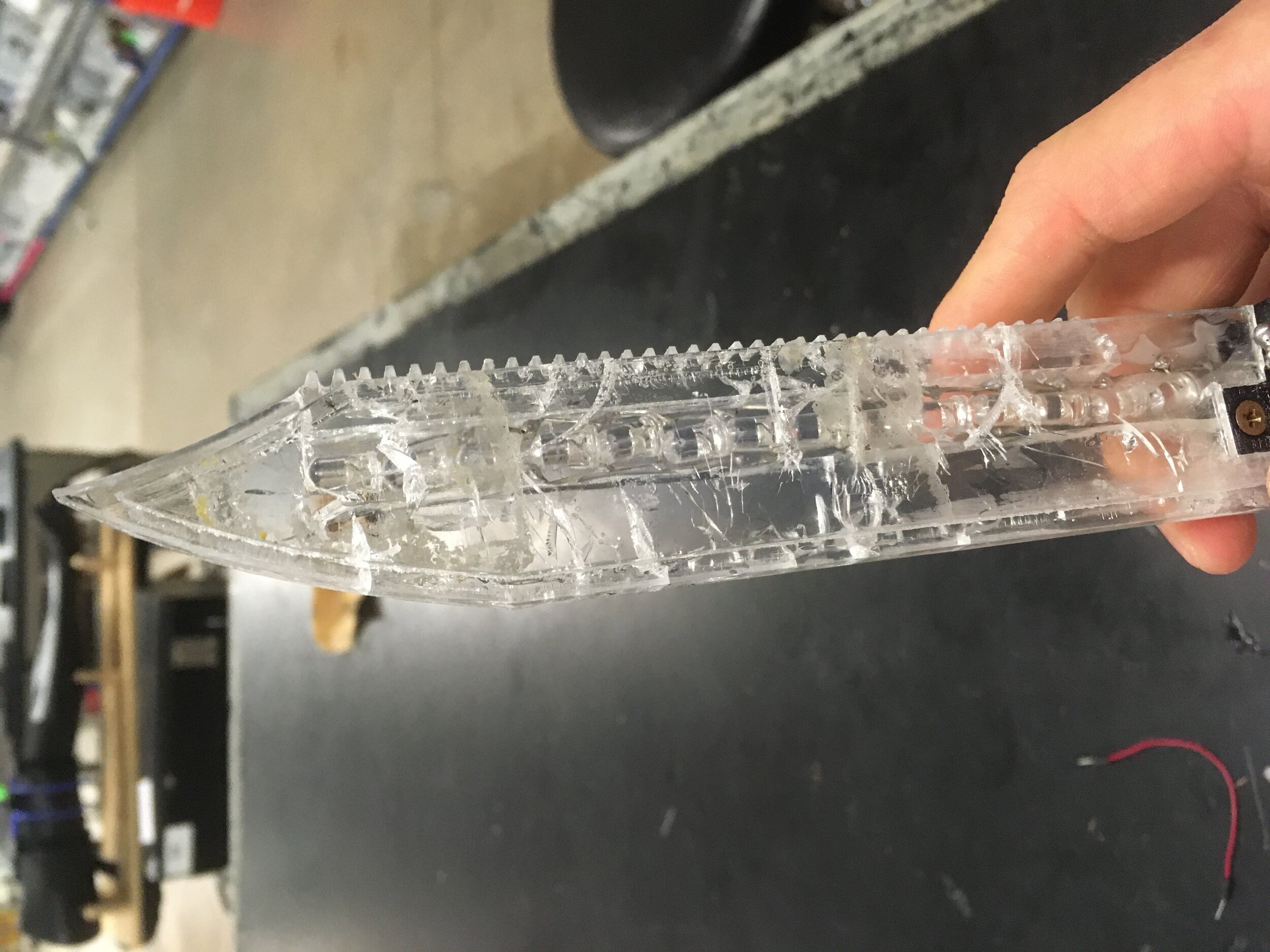


The clamping process ended up fracturing the acrylic at multiple points, but I didn’t mind! I thought it actually looked kind of cool, like some kind of corrupted blade with an edgy backstory.
After that, I ground the 3-layer composite down to a knife edge using a belt sander. Even included a subtle drop point on the top side of the blade. This is for more effective stabbing in real knives, but I included it because (you guessed it) I thought it looked cool.
Looks awesome powered on!

Here I am lathing metal contact sliders to be able to from carry current from the rails to blade LEDs.
While I could have hard-wired directly to the LEDs, due to the sliding nature of the blade, it would have meant leaving a lot of slack in the wire, and trailing wires don’t look good. Plus I just wanted to flex my engineering muscles.
In retrospect I should have used carbon brushes, but ¯\_(ツ)_/¯!


Press fitting the lathed inserts into a 3D-printed blade sliding bracket.
Bracket installed. You can see the LED bulb strand as well!
I hadn’t heard of neopixels or other individually-addressable LED strips at the time, was just doing what I knew from making hobby lightsabers.
Looks absolutely great all lit up!

Test driving the gear train and sliding electrical contact system. Pretty damn badass.
electronics & Control
Since there were a lot of things going on in this project, I needed some way to manage it all. I spent the summer learning Arduino and coding controls for all my inputs and outputs.

Here is a portion of my code. I just followed tutorials and trial-and-errored everything until it worked.
Basically, once the Arduino is powered on, it stays in standby until one of two modes is selected: Shoot or Slash. These were toggled by momentary switches, and actually caused some problems (more on that later).
From there, two microswitches mounted on my index finger control the flywheels/roller, or blade extension/retraction, depending on the mode.
In addition, I also included a set of limit switches with the blade system, to stop the blade motor once it was fully extended or retracted. This way I could prevent burning out my motor and breaking gear teeth.

I used an Arduino Nano clone to run my program, and a LM2596 buck converter to power it. My main power source was a 3S (11.1v) lipo battery.
I could have used a linear voltage regulator to drop the 11.1v to the Arduino’s required 5v, but from my research they seemed to be less efficient than buck converters. The 3S battery was chosen (as opposed to something closer to 5v) because my motors all ran on 12v.


(1) Since I didn’t know how to mill PCBs yet, I wired everything by hand on a permaproto board.
(This picture was totally not taken in a bathroom.)
(2) The backside of the board! If you look closely, you’ll see some traces dremeled away. I did this to subdivide groups of traces into my own custom ‘zones’ so I could fit more components in.
(3) Completed circuit board!
I added connectors to the end of each wire so I could easily connect components for testing, but still disconnect everything before the final assembly.
The green board is an H-bridge motor driver. It let me run one of my gearmotors in both forward and reverse to drive my retractable blade.

Testing the program with all components temporarily connected.
This took a few tries, and I had to rewrite the code quite a few times.

Finally, after everything worked as intended, I mounted the board in a 3D-printed tray, rewired all the cables to the correct lengths for mounting, then bundled them together according to their destinations.

Final Assembly
With all subsystems tested and working (and with summer coming to a close), I raced to finally finish this project.
Timelapse of physical component assembly!
Take a look!

I included channels in my design for wires to pass through without being exposed.
In this photo you can see the leads for the flywheel and roller motors going through their housing in the wrist block.

I housed my battery and power buttons in a compartment in the hinged wrist cuff mentioned earlier. This was a much more efficient use of space than having it just be a solid block of plastic.
These switches are actually inaccessible when the compartment is locked into place around the wrist, and are only usable when the hinge is unlatched for wearing or removing the gauntlet.
Which in practice are the only times you would be powering it on or off anyway. The hinged compartment locks in with a spring-loaded pin and magnets.

Many zip ties were used to secure wire bundles to the long M6 bolts.
In this way the bolts acted as both a skeleton for the physical structure and anchor points for the wiring.

All cables connected, moments before final assembly.

Here is the wiring loom installed. The box with the two nuts is the tray for my circuit board, where it sits facing outward.
I left a hole in the back for a Mini-USB, so I can actually reprogram this gauntlet on the fly (to adjust ROF or scale down autocannon power).
Finished!

Here’s a demonstration video of the whole thing completed! (Or actually not quite, as explored in the next few slides)
I’ll embed another, more comprehensive walkaround video when I have time.

As mentioned earlier, my code / electronics implementation had some glaring problems.
As I wasn’t an advanced programmer at that point, I made the mistake of not including any timing or debounce in reading the mode select button presses. This meant the program never double-checked whether a button was actually pressed or not before performing actions.
While theoretically this shouldn’t have been a problem, in reality with electronics there is always random noise and fluctuations, and even a small blip might be read as an intentional button press.
Of course I didn’t know any of this back then, and was just plain confused at why SAGA would do the wrong things at the wrong times.

I solved the problem by developing a new switch panel, using a latching switch instead of 2 momentary ones.
I reasoned that part of the underlying problem was that momentary switches return to their default position / signal when released, meaning that even after I set a mode, it wouldn’t be maintained and any voltage fluctuation could overwrite it.
Though this could easily have been fixed in code, at the time I opted for a hardware fix. I noticed that if I held the momentary buttons down while firing, the signal wouldn’t flicker and the gauntlet wouldn’t switch from one mode to another.
So I simply implemented that with a switch that would hold itself - i.e. a latching switch! Honestly, this should have been the design from the start. But i was new at the time so ¯\_(ツ)_/¯

Incidentally, the new switches I used were actually harvested from the old Rice Solar Car!
Well, before we uh... decommissioned it with extreme prejudice 😅

Here is the new switch and panel all installed!
I switched to a yellow switch because I actually broke the earlier blue one. Whoops
The green numbers are a battery voltmeter, though it’s more for aesthetics than anything else.


And with that, SAGA was finally finished - For real this time!
With that done, it was time for some good old-fashioned field testing!
Extras

I got to field test SAGA at the 2019 Halloween Critical Mass!
Critical Mass is a massive group bike ride that happens every month in Houston (other cities, too). The Halloween ride was special, because everyone dressed up and decked their bikes out with lights and speakers.
I got to joust with some other riders, cross swords with a Negan cosplayer, and shoot my gauntlet at inconsiderate cars who swerved too close to the riders.
It was a very cool experience, and I collected valuable combat data to build into SAGA MK II.
(also feat. the MagnaSaber and the ShootStyle leg armor)

Critical Mass getup, with better lighting

My buddy Pat wearing a still-WIP S.A.G.A!
There was also another time where my dorm lost power and I thought it appropriate to get geared up and make a fool of myself.
A good friend got it all on video and sent it to me.
Good times. I will miss them :’)

A gallery of my concept sketches! I’m quite proud of them.


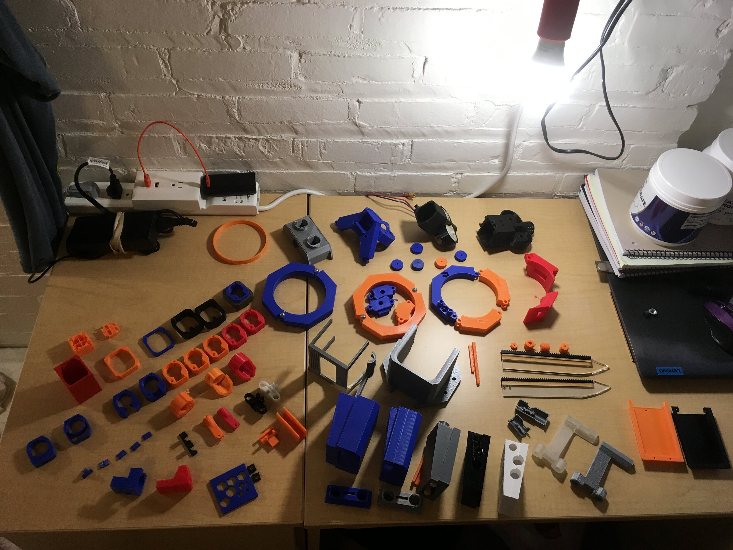


And all the prototypes I went through to make SAGA. You can tell there was a LOT I cut out for brevity.


In the end, I decommissioned SAGA and put it into long-term storage. It probably won’t be unearthed again.
Press F to pay respects

End of Evangelion SAGA
But that’s not to say it won’t be missed!
SAGA served its purpose. It taught me so many new skills, and started me down the path I’m on now.
SAGA was my 初号機, my first machine. In many ways, it reflects myself as a creator (well duh) - edgy as fuck, rough around the corners, and way too ambitious. But from underneath that, other things shine through too - a ton of creativity, curiosity, and ability to spin together disparate elements of my life into a single, unified vision.
SAGA will return.