
b.reakthrough
a.utomated
k.annon
i.nstrument
[full spec]
Heads up! This project is still a WIP, at around 90% completion. Though it’s not entirely finished, I’ve decided to publish the writeup as-is, as there’s still a lot of cool systems developed and discussed. I’m hoping it’ll also show off some recent project work to recruiters (👀)

Shoulder Cannons. One of my absolute favorite tropes in mecha anime and fiction in general.
In addition to basically acting as an extra appendage, being able to leisurely target and blast away with it just seems so cool to me.
The idea of doing all that standing still, not even lifting a finger, and the implication that your opponent isn’t even worth that effort — like fuck dude, what a power move!


Mobile Suit Gundam, Evangelion, Rockman.EXE, One Punch Man, Halo, Pokemon — If a franchise doesn’t have shoulder cannons, it’s a pretty safe bet that I’ll have no interest in it whatsoever 😅

So… I decided to make one for myself! What did you expect?
Enter B.A.K.I. (Breakthrough Automated Kannon Instrument) — a computer vision auto-tracking shoulder cannon!

As the name suggests, B.A.K.I. is the evolution of b.a.k.i. — my first computer vision auto turret!
From the beginning, b.a.k.i. was intended to be a stepping stone for B.A.K.I., and I was able to apply everything I learned in that proof of concept into this new, full-spec version!
I designed it to be superior in every possible metric — reaction time, output power, range of capabilities, and general aesthetics 👌🏽

As this is a pretty bananas 🍌 build, I’ve organized this writeup into subsystem-based sections. If there are ‘continuity’ errors between sections, that’s because most systems were actually developed concurrently; I’ve just decided to sacrifice chronology for clarity instead:
Overview
Bakugo Shoulder Bracket
Cannon Body + Firing System
Barrel Rotation Mechanism
AirLift Ammunition Feed System
Dual Axis Rotation Apparatus
Linear Deployment Rail
LASERs!
Computer Vision
Electronics
Integration / Test
Printed Circuit Board (PCB)
overview

A shoulder cannon sits on the shoulders!
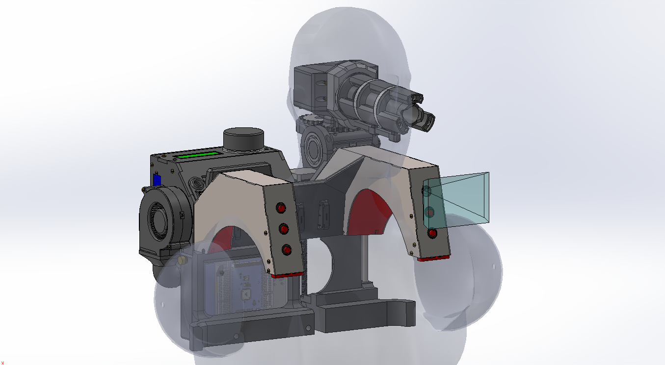
Therefore, the centerpiece of Project: B.A.K.I. is an aluminum shoulder mount, that attaches to standalone backpack and cannon units.
Various mode-select switches are embedded inside the shoulder mount, as well as a camera for the computer vision function to ‘see’ and target things. The bluish pyramid beaming out from the left shoulder is the camera’s field of view. This CAD assembly has over 400 components!! 😫😭

The backpack serves as an ammunition reservoir & delivery system. It uses an agitator and blower fan to airfeed foam Nerf balls from the reservoir to the cannon via a hose.
More importantly, though, it also contains all the computing elements, and links to both the cannon and shoulder mount using a series of cables.

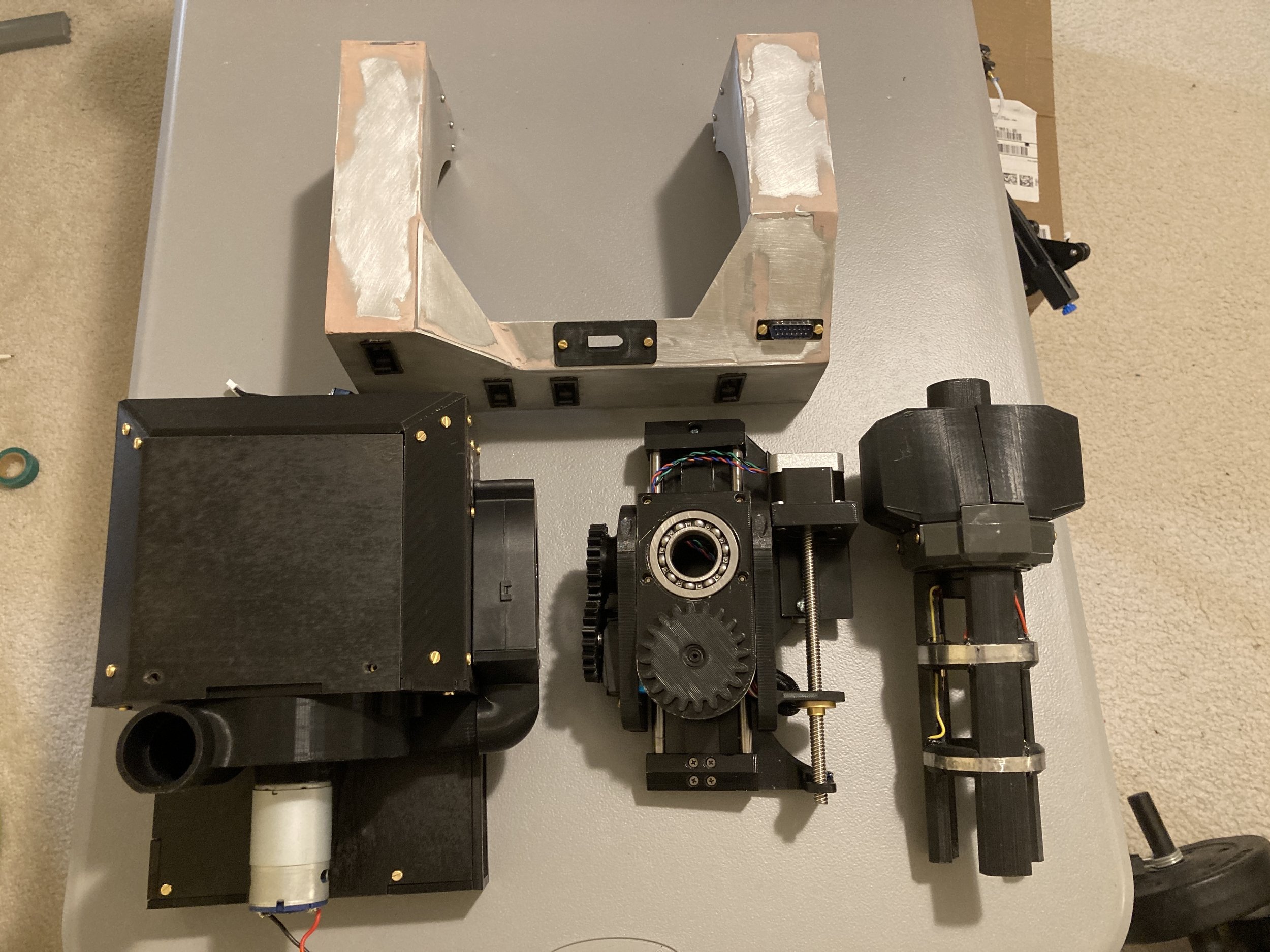
The cannon was the most mechanically difficult part of this build. This assembly contains 9 motors, used to:
Deploy the cannon carriage from a ‘racked’ position to an ‘active’ one
Aim the cannon in horizontal and vertical directions for targeting
Spin the tri-minigun barrels (with embedded lasers!)
Fire soft Nerf ball ammunition

Finally, B.A.K.I. was designed to operate in 2 different modes:
Auto Mode: Computer Vision - track and shoot at designated target signatures, as recognized by onboard camera
Manual Mode: Joystick Override - direct user control through a Wii Nunchuk (yup BAKI is Nintendo-compatible 😎)
(Secret Mode) - will be revealed in a later update!
shoulder bracket

For certain reasons (AKA I am a massive weeb), I wanted my shoulder mount to look like Bakugo’s neck brace from My Hero Academia. Design elements to note are the metal-looking construction, and decorative holes in the front and side faces.
In order to steal his look…


…I started with a cardboard template! It’s my go-to first step in any project.
After cutting and trimming until I was satisfied with the fit, I took measurements and used them to make 3D drawings!


In addition, I took careful measurements of my trapeziuses (trapezii? trapeziums?? — shrug muscles 👍) to create some liners that would sit over them. I left a little bit of wiggle room for leaning out / bulking up between training seasons too!


Using my cardboard thingy for reference, I modelled panels to laser cut out of 5mm thick plywood! The finger joints along the edges are meant to lock together and eliminate the need for internal bracketry.
Buuuttt… then I thought, ‘how badass would it be if I made the mount out of aluminum instead?’
I completely redesigned the shoulder bracket to be made out of 1/16” aluminum sheet. It’s much sleeker and lighter, and this way it’d also be silver-colored, just like how Bakugo’s brace actually is!


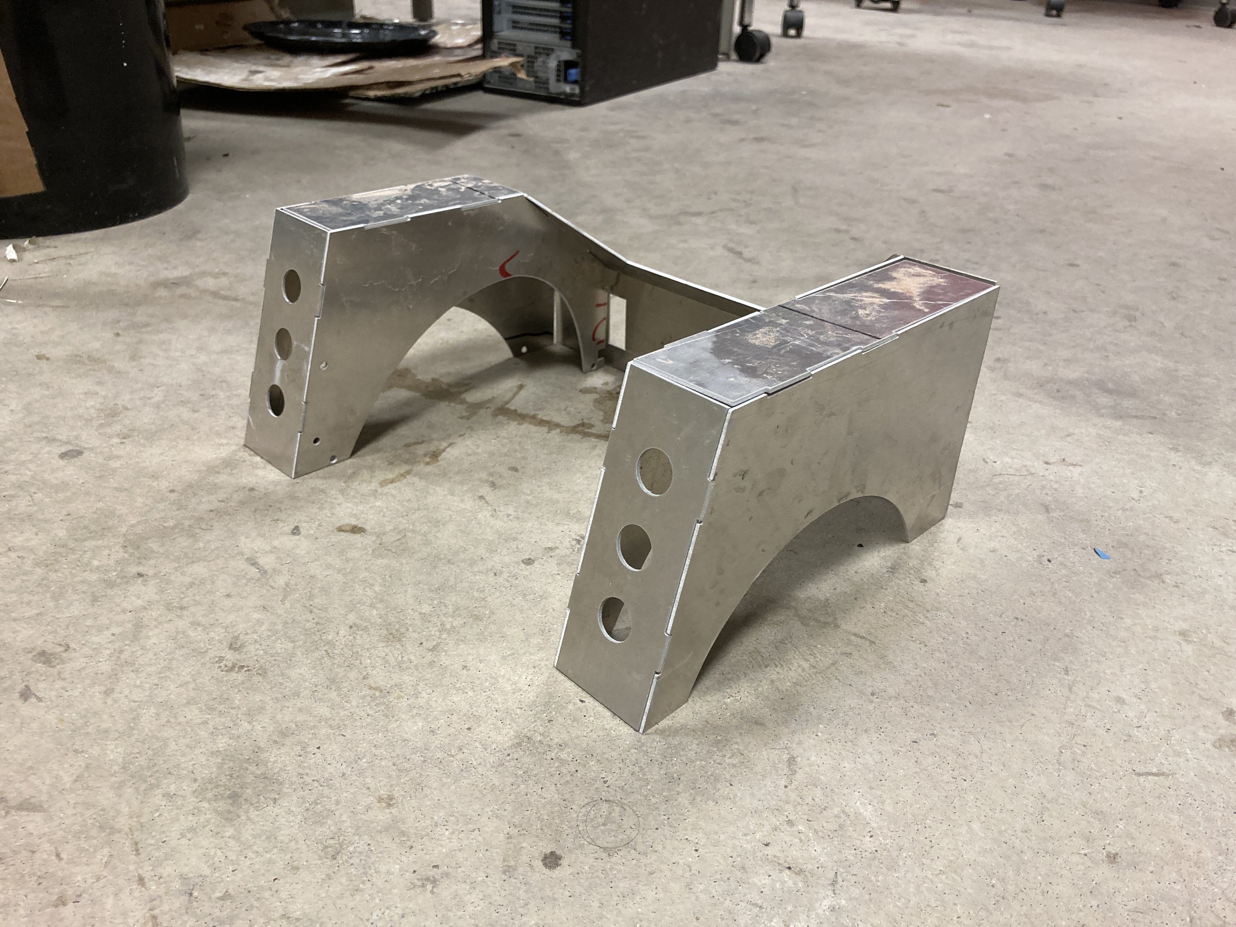
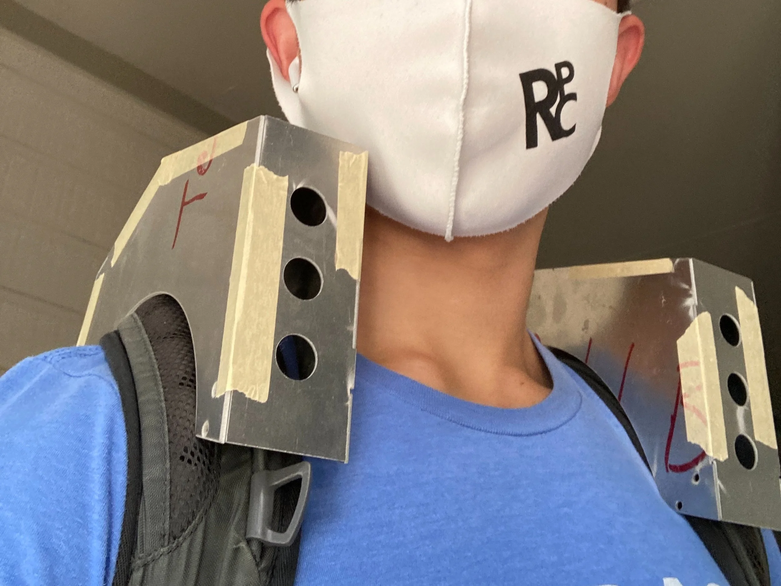
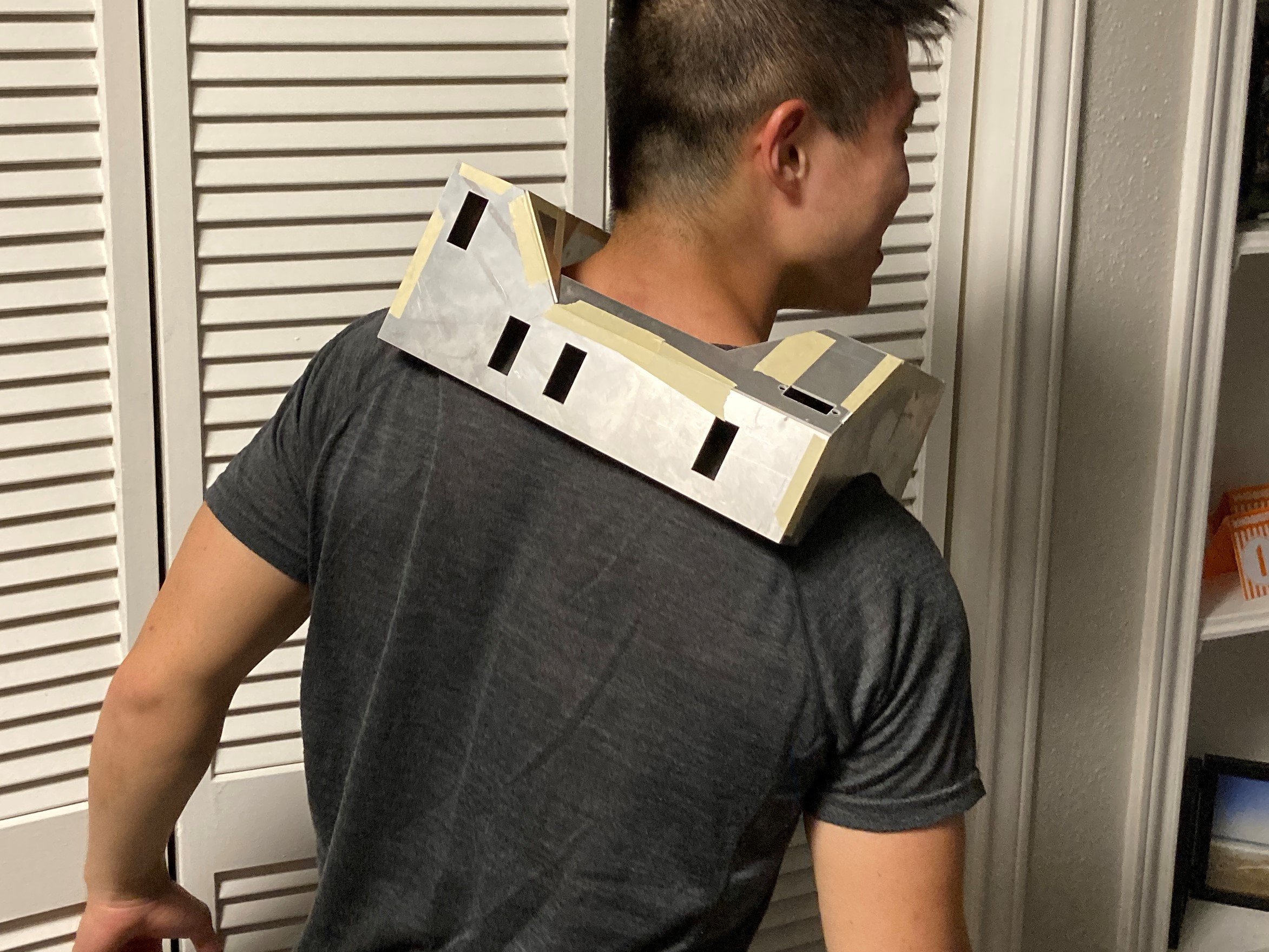
I mocked everything up, taped it together, and put it on. Hell yea - it looked and fit great!
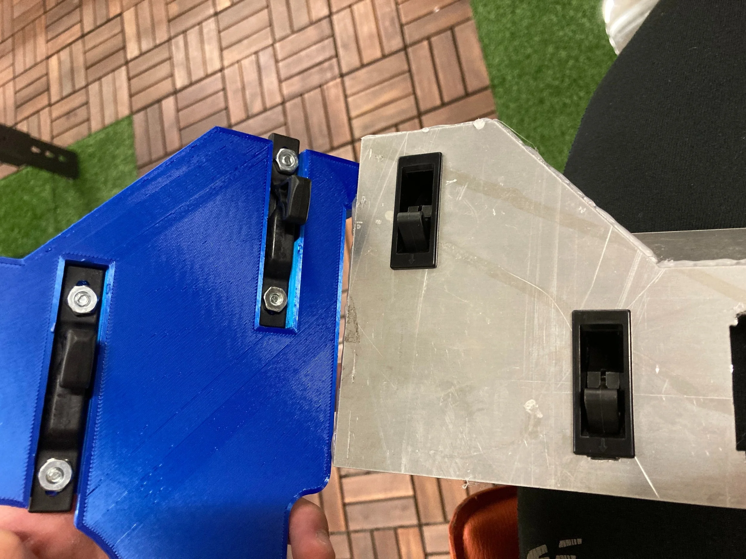
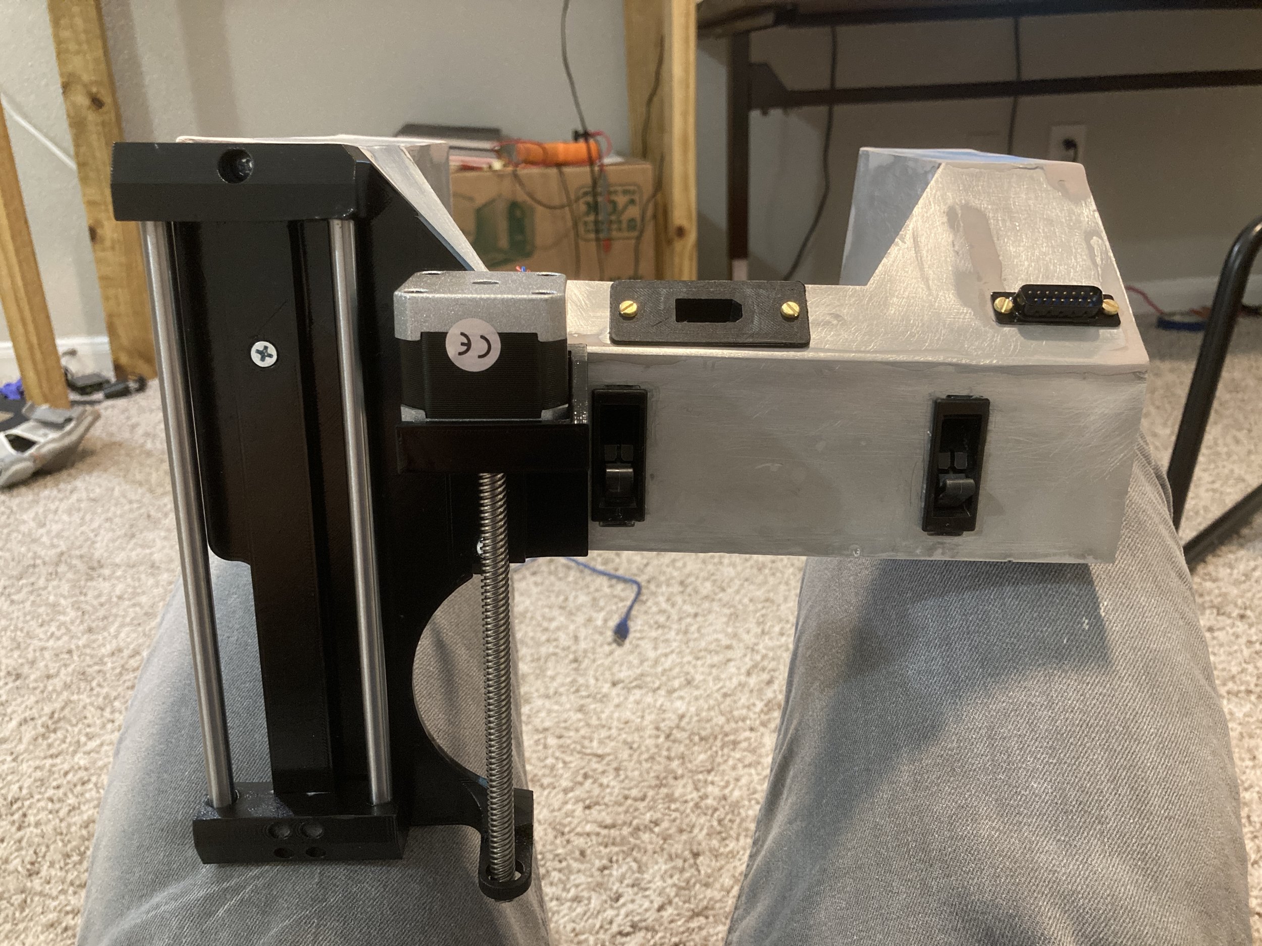
(The rectangular holes in the back are for quick-release mounts for the backpack and cannon)
My next step would be to replace the tape with a more permanent solution. I decided to weld everything.
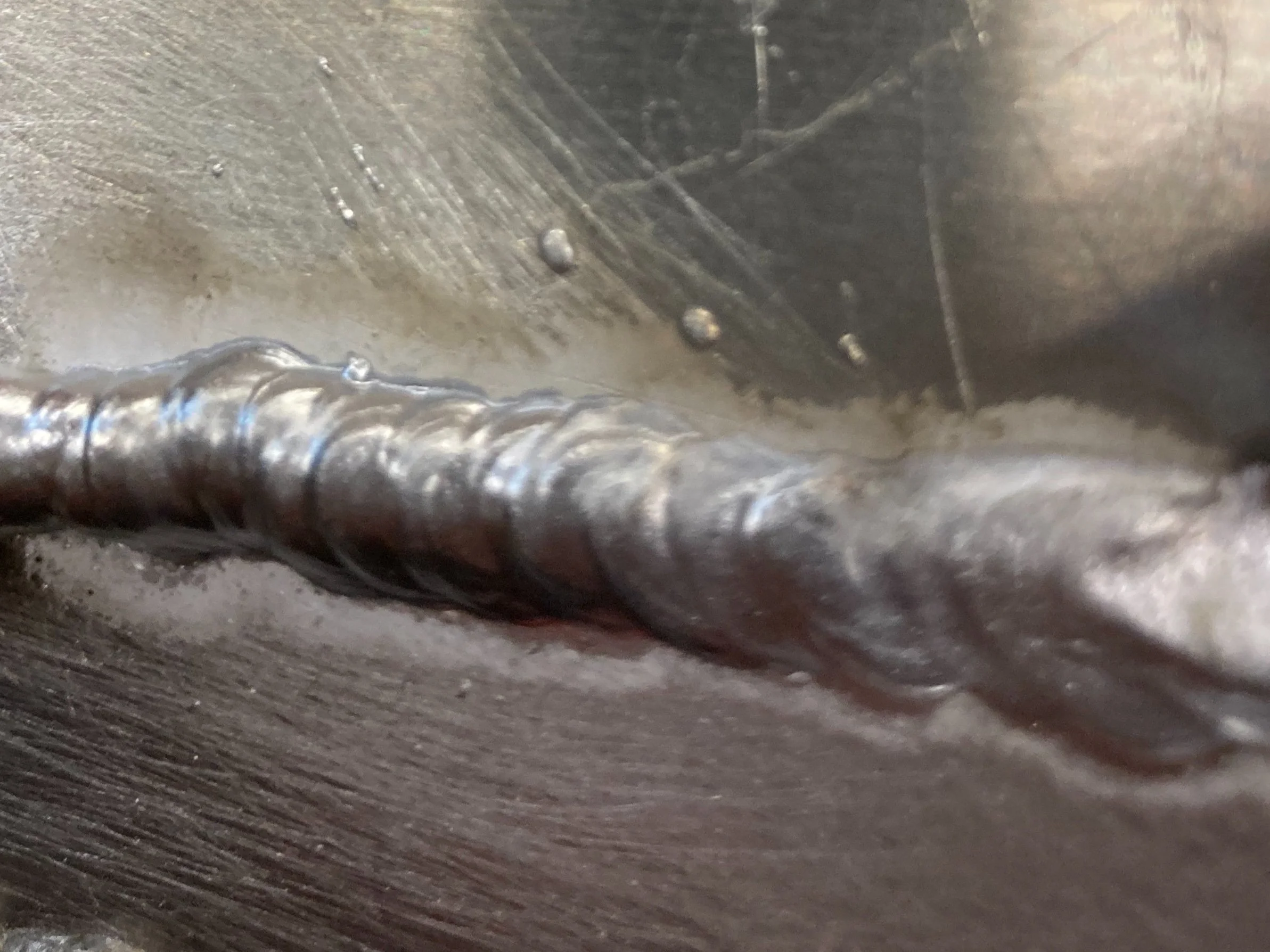


For those who don’t know, aluminum’s atomic properties make it difficult to weld — The main reason being its tendency to form an oxidation layer that is difficult to penetrate. Other concerns include porosity and low melting point, etc.
Despite being warned of these difficulties, I tried a practice piece and it turned out to be pretty easy, so I decided to go for it!
Before I welded everything together, I added some framing inside for more rigidity + strength.
After welding, I threw on a coat of auto body filler to fix the slight tolerance gaps from waterjetting, and sanded everything flat!
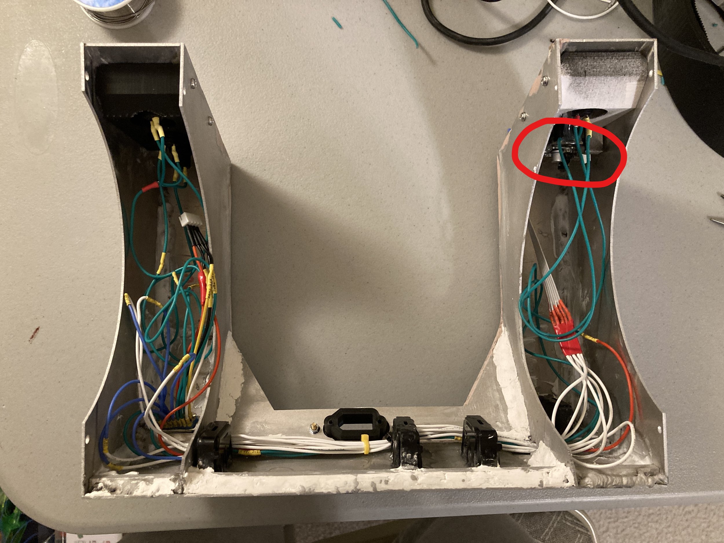
After I had the shoulder mount fabricated, I populated the insides with electronics: a camera module (circled in red) and 5 pushbutton switches for various actions (selecting modes, triggering actions, etc.). And lots of wires of course!
And with the 3DP liners installed, everything was perfectly hidden away for a neat, presentable exterior.
Really putting the ‘embedded’ in embedded systems here 😤

At some point, I sprayed on some metallic silver to cover the pink body filler. It’s not quite a mirror finish, but is reflective enough (see my left shoulder and the reflected orange stripe).
BOOM - One completed shoulder cannon mount, complete! I can also wear it as a standalone piece for cosplays.
(That’s actually the entire reason I wanted the other backpack and cannon units to be quick-detachable haha 💀)
[k]annon + firing system
As mentioned before, and like my previous projects, BAKI uses a flywheel system to launch compressible foam Nerf balls.
The gifs above show how two wheels grip the rounds and use friction to accelerate them, flinging them out of my cannon!
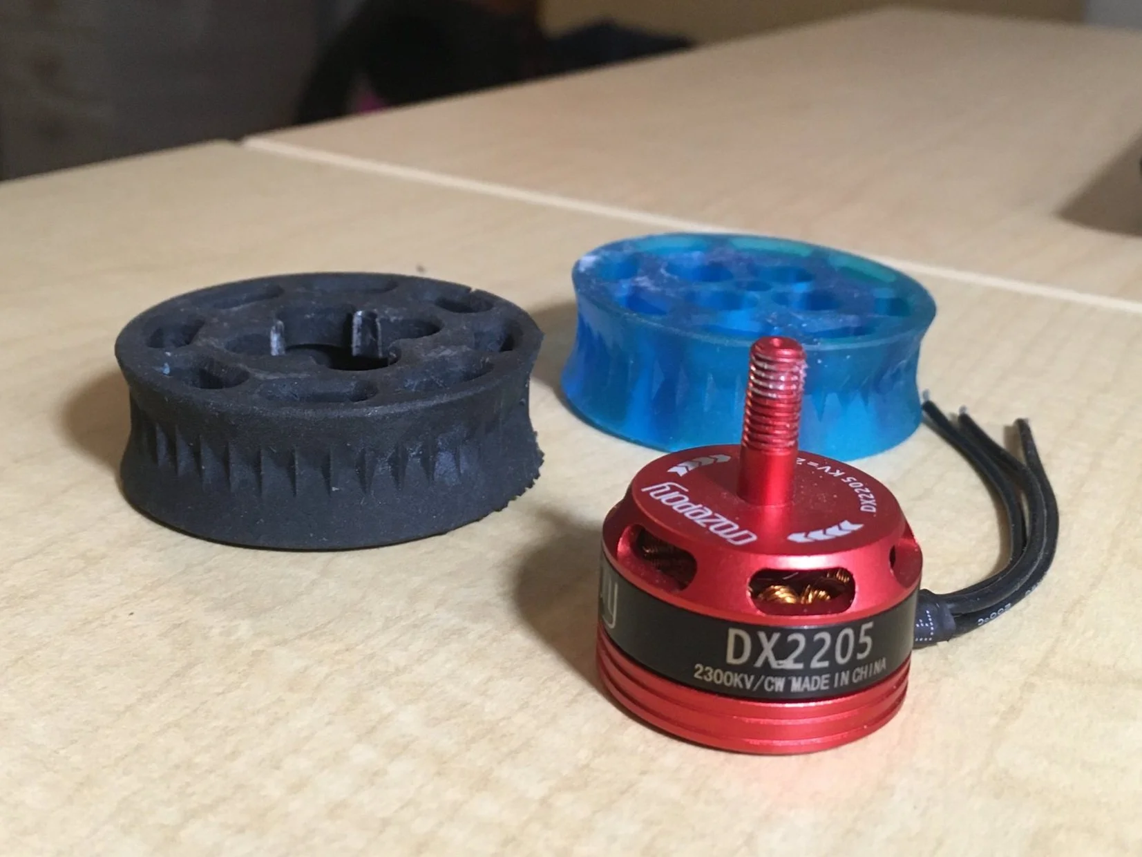
Unlike the previous SAGA and baki builds, I’m using brushless drone motors to spin them this time!


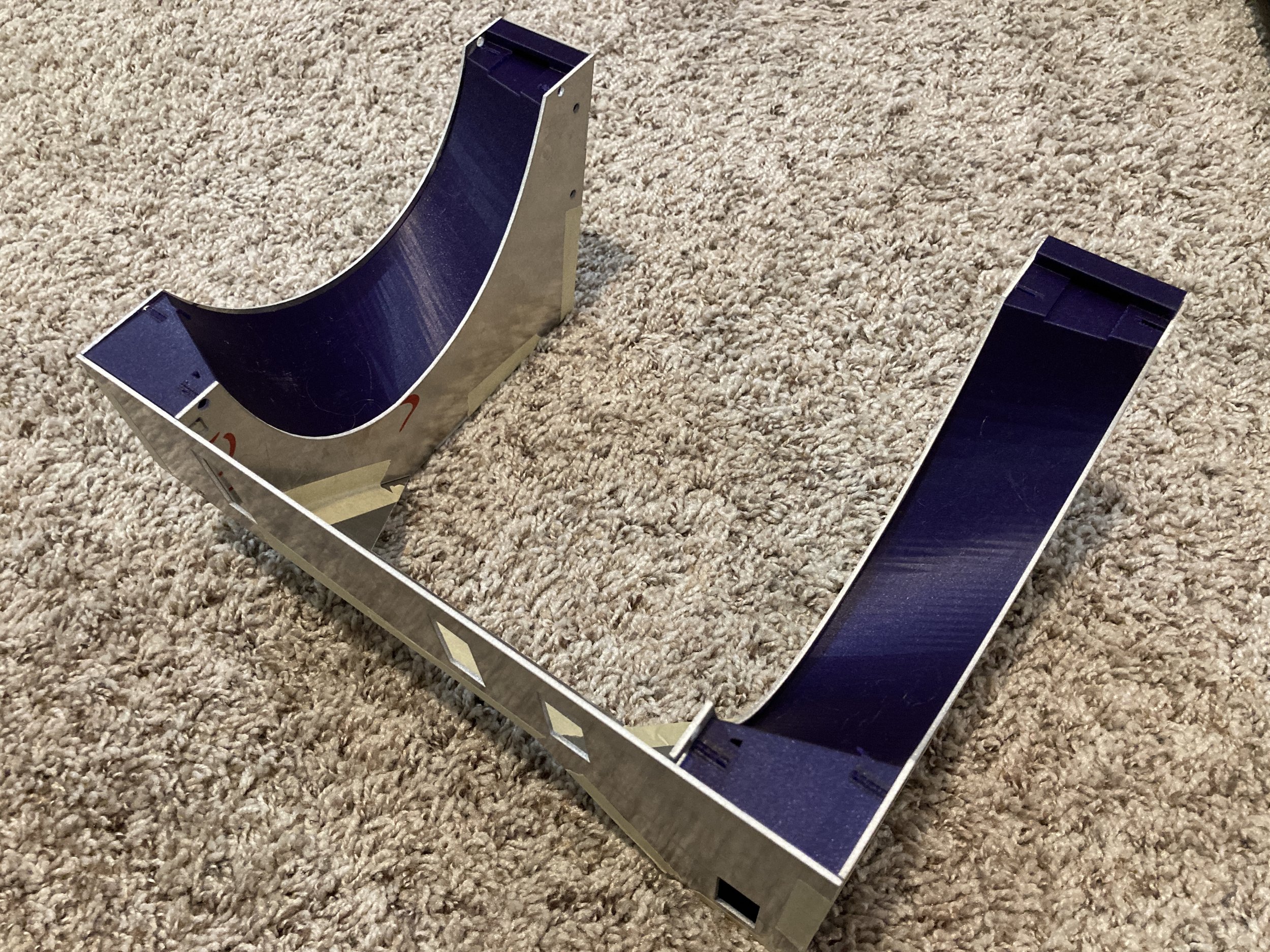
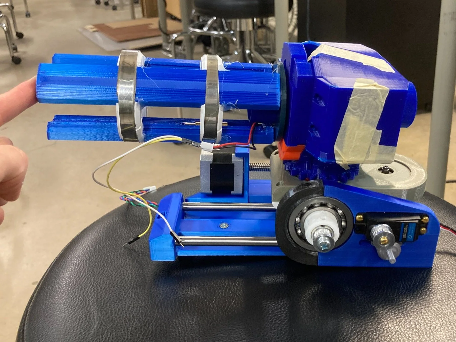
To house the flywheels, I designed a cannon ‘pod’ unit. Here is a CAD model, and a very early 3DP version (still taped together).
The orange arrows show the path of the balls as delivered by the Airlift system (covered later), accelerated by the flywheels, and blasted out the front!

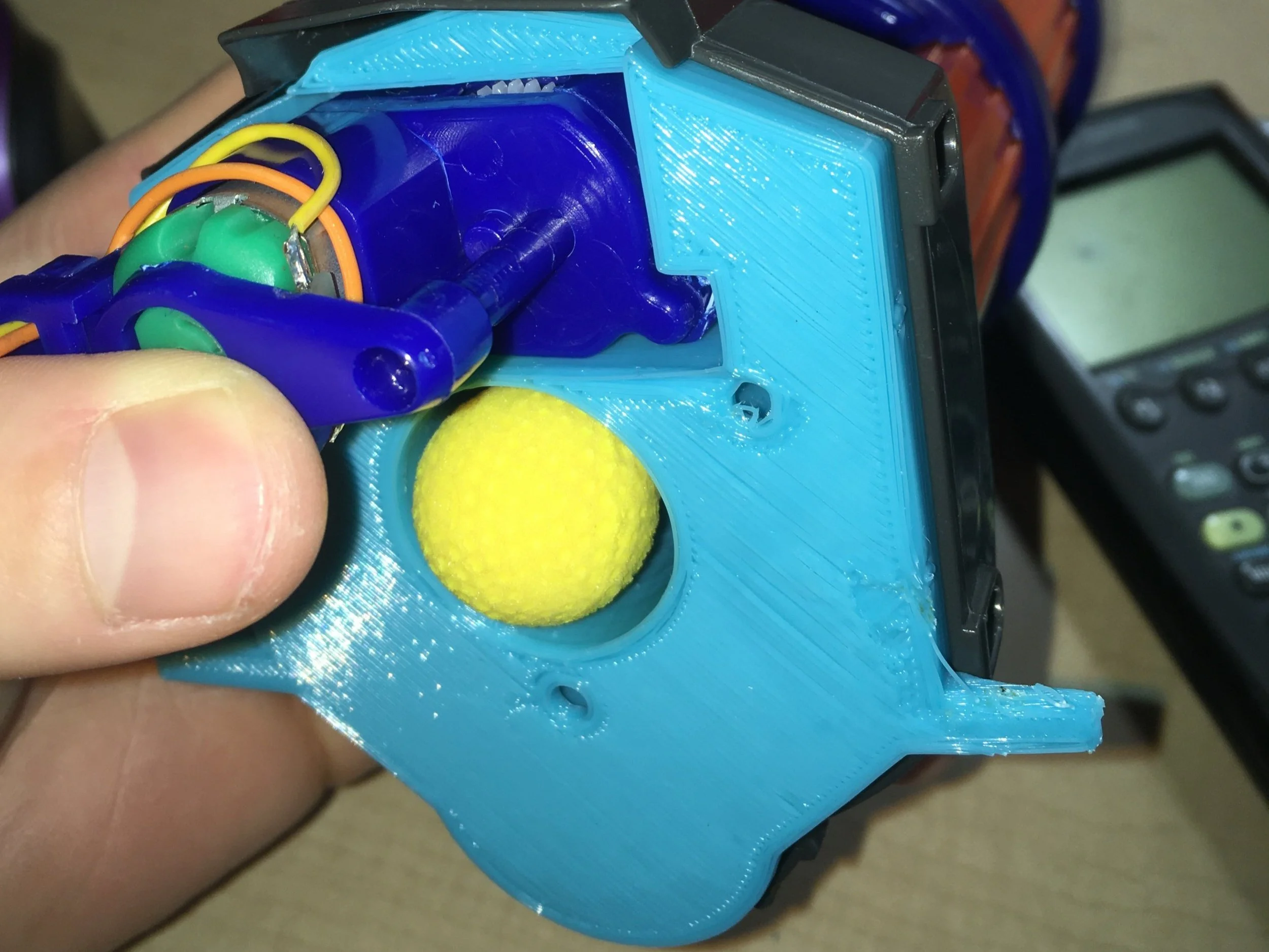
Fully assembled cannon pod internals!
In addition to the 2 visible blue flywheels, there is one other serrated blue index wheel. This is part of the fire control system!
It serves as a gate to block the incoming stream of balls from entering the flywheels when the cannon shouldn’t fire, and spins to squish-feed them through when it should. The animation should somewhat explain this.
Also, the black pipe looking thing is the acceptor for the ammo feed hose mentioned before.

Testing flywheel as installed in a further-along cannon.
I only connected one motor for testing; I already knew they worked, so this was just me reducing the number of things I’d have to wire before final assembly.
But yea, Flywheel launching system, complete!!
Barrel Rotation mechanism

An important skill in any project is kitbashing, or borrowing existing components from other things around you! It basically means resourcefulness, but y’know, buzzwords 🙌
The toy shown is the Dart Zone Scorpion blaster! The idea of sticking one of these on my shoulder was what inspired this project to begin with, so you bet I was going to buy one and kitbash the hell out of it.

Naturally, the first thing I did with mine was to BREAK IT IN HALF!!!
The only element I intended to harvest from the Scorpion was its barrel rotation mechanism. Everything else about BAKI (flywheel motor type, orientation, spacing ammunition type, etc.) would be too different, so it made more sense to develop solutions for those from the ground up, instead of adapting store-bought ones.
So I just yoinked the gearbox, dismantled the rest, and put them in a box for later (never).

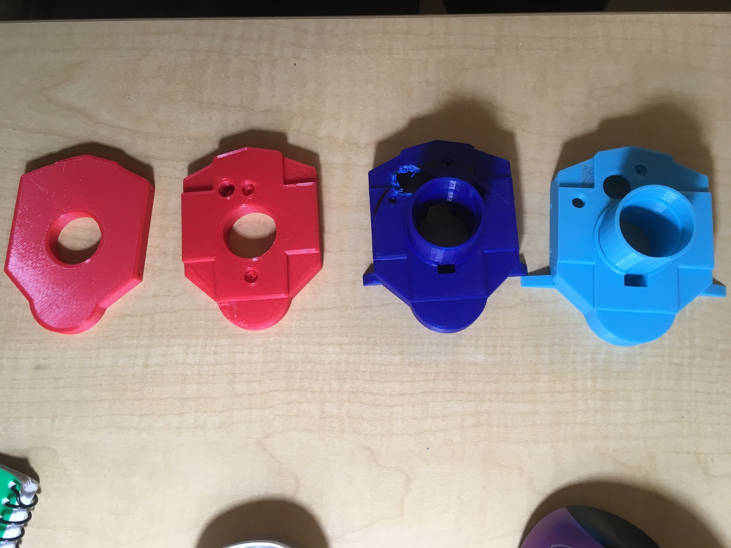
Next, to bolt up my stolen gearbox & Scorpion barrels for use in BAKI, I needed to reverse-engineer some mounts!
Using some approximate dimensions, I trial-and-errored a series of 3D-printed ‘plug’ adapters that fit my parts.

I gave the motor 6V and stood back to watch some spinny minigun goodness!
Guys! We just made a standalone barrel rotation system!
Oh man, just imagine this whirring above your left shoulder 😩😁

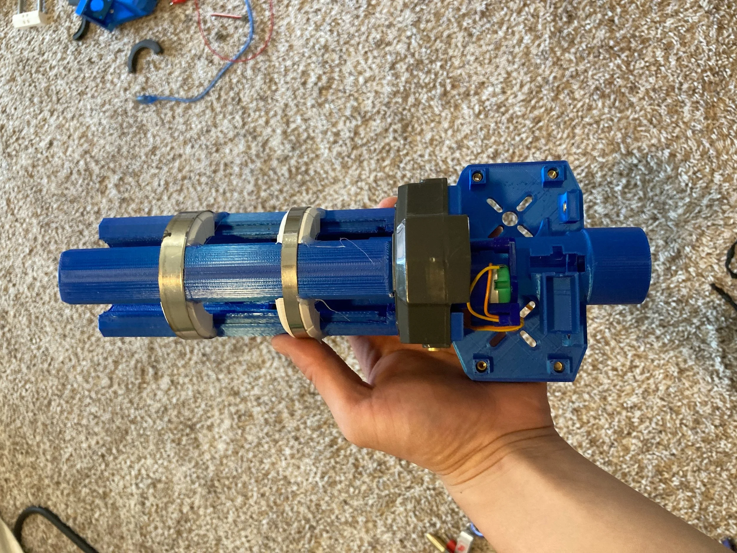

Eventually, OCD got the better of me and I designed a cooler version of the tri-barrels!
Here’s a progression from CAD model to preliminary print, and then to final cannon tri-barrel + pod assembly. Looks mean as heck!
What are those metal rings, you ask? Hmm, I sure wonder…

And once again, a clip of the updated tri-barrels spinning.

Relevant lol
Airlift Ammo Feed System


Now that I’d figured out how to shoot balls from my cannon, I needed to work backwards: How would I physically get balls to it??
Well, as a veteran Nerf gun modder (😤👌🏽), I’ve seen a lot of creative solutions in my hobby. One that I thought work would work perfectly for this application was TorukMakto4’s hopper-fed Zeus modification!
To replace the stock Zeus magazine with a higher-capacity hopper, Toruk developed an agitator design! It works like a blender - basically using a spinner to agitate balls and having them fall through a feed tube. He boasts that this setup has not jammed once.
I decided to take heavy inspiration from this for my own ammo feeding mechanism.

While an agitator worked great for a purely gravity-driven system, it wouldn’t work for my project. Not as-is, at least.
Last I checked, your shoulder is higher up than your back, so an ammo feed system trying to send balls from a backpack unit to a shoulder cannon would need to work against gravity! This was something Toruk’s project hadn’t needed to account for, but I had to contend with in my design.
Luckily, Bui1derBB had solved that for me! His ‘Junk Jank Proton Pack,’ used a mattress inflator fan to airfeed balls up a hose to a Zeus blaster, allowing it to both feed against gravity as well as unleash a veritable storm of foam. That rate of fire is insane.
His documentation albums and advice when I messaged him (super nice + helpful!) led me to pursue this solution for BAKI.


With proven concepts from my fellow modders, I set out to make my own derivative.
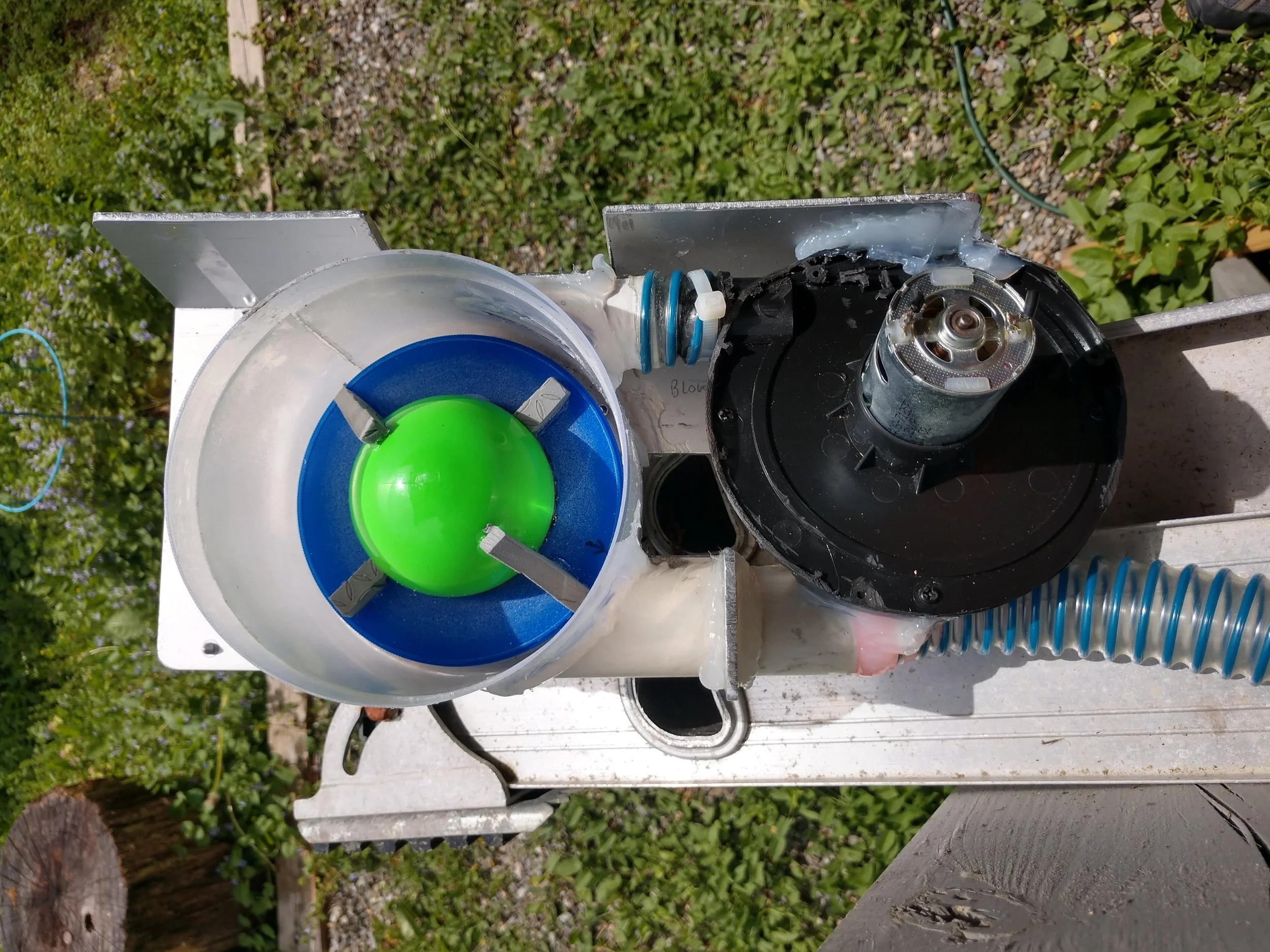
I bought a Coleman 12V mattress inflator, cut away everything but the motor and fan, and connected it to my own agitator design!
For the agitator, I basically replicated what Toruk and Bui1derBB had designed with 3DP parts: An orange cylindrical drum with inlets/outlets, and a 6-pointed ‘spinner’ in its center!
The fan forces air into the drum, which joins the exiting stream of balls, giving them additional propulsion as they leave the outlet port.

Before I could properly test my system, COVID happened and we were all sent home from school.
Now again without tools or materials, I was forced to improvise with the few parts I had managed to fly home (TSA was confused but let me through) and household materials.
So I grabbed a cardboard box, some hot glue, and plenty of tape to make a test hopper!
Though this test was super jank and unoptimized (poor seal with cardboard box, even with taped seams, as well as balls getting stuck in the rectangular corners), it was an important step in developing my ammo feed system.


After we returned to in-person school, I went back and redesigned with new ideas in mind:
(1) I got smart and bought a brushless fan instead of the mattress inflator, to increase efficiency and reduce noise!
(2) Also modelled a reducer to funnel the airflow into the agitator.
(3) I refined the agitator design a bit more, adding actual threaded mounting flanges.

To make sure my new brushless fan would be able to feed balls against gravity…
Here I am doing a quick test! I connected my fan+agitator combo to the longest length of hose I could find, and confirmed that it could blow balls at least 4’ vertically! (Apologies for the atrociously messy room; this is what full project-mode Brian looks like.)
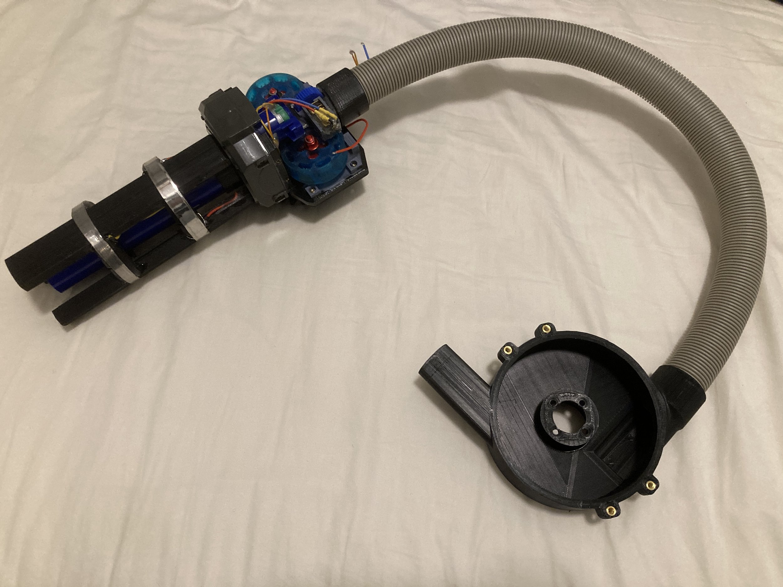
And finally a pic of the planned hose connection between backpack (represented by just the agitator drum) and cannon.

Now with all critical functionality confirmed, I felt confident moving forward and committing to further design work.
I drew up and laser cut a backpack / ammo reservoir out of 5mm plywood!
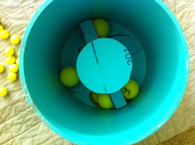
I taped it up, added a sloped 3DP inner piece for more consistent feeding, and bolted on the agitator assembly. Then I plugged it in.
Holy smokes 🚬, this thing fed so well!! Just look how quickly that entire hopper of balls got spat out!

Finally, I cleaned everything up to look more professional.
Here is the updated backpack, with a panel removed to show the spinner, and the motor powering it underneath.
The thing on top is a bottlecap - my solution for unscrewing and pouring in more ammo!
Airlift system - complete!
dual axis rotation
In order for my cannon to work properly, it needed the ability to pan and tilt to properly target things!
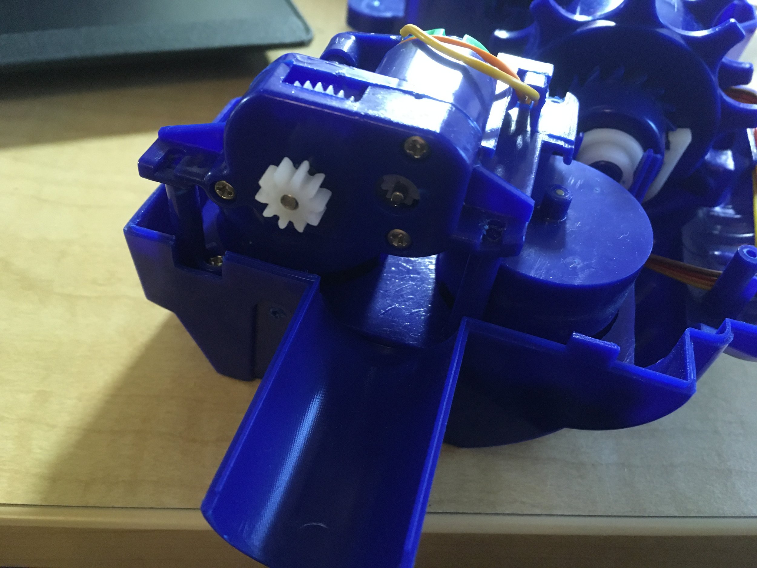
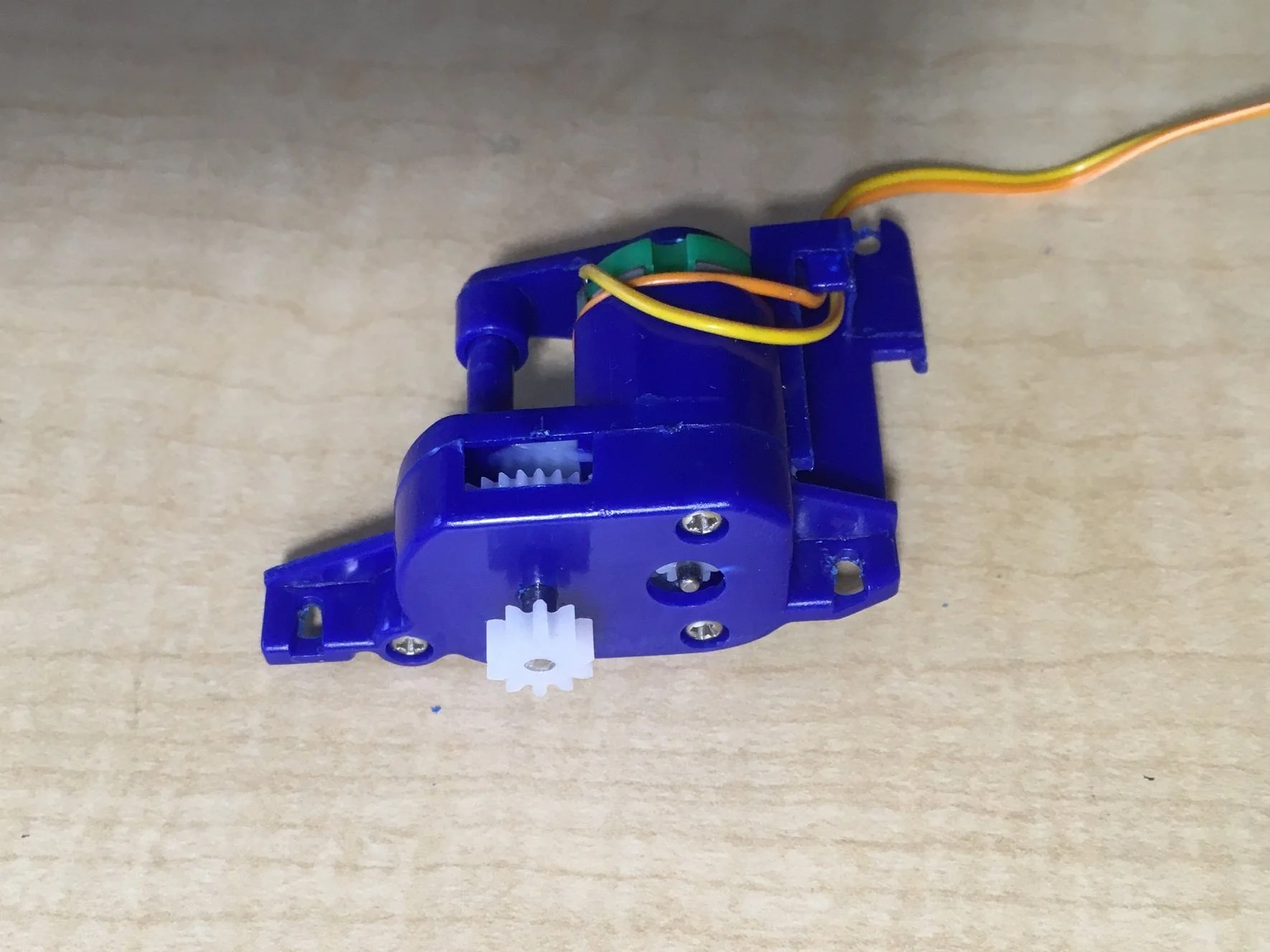
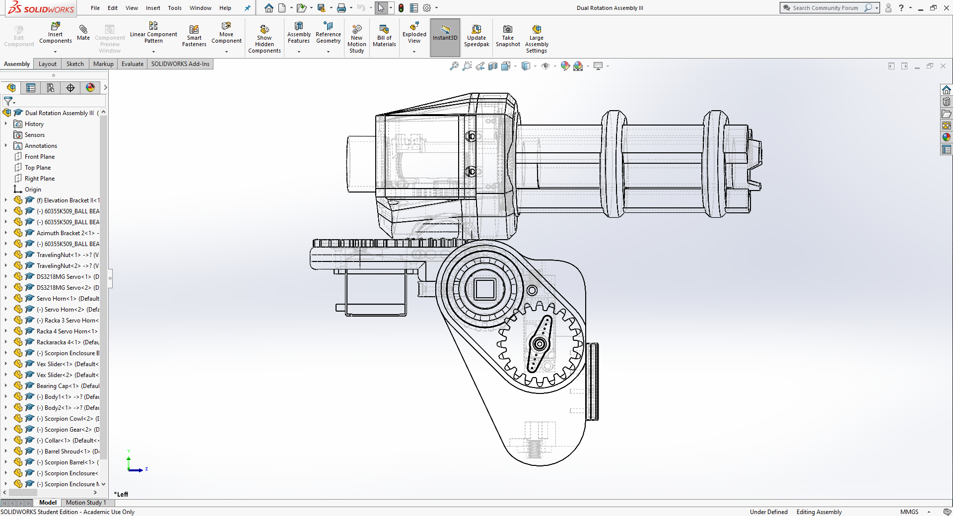
Here is an early design showing roughly how the system works. One servo motor controls the elevation (vertical) orientation of the cannon, and another controls the azimuth (horizontal)!
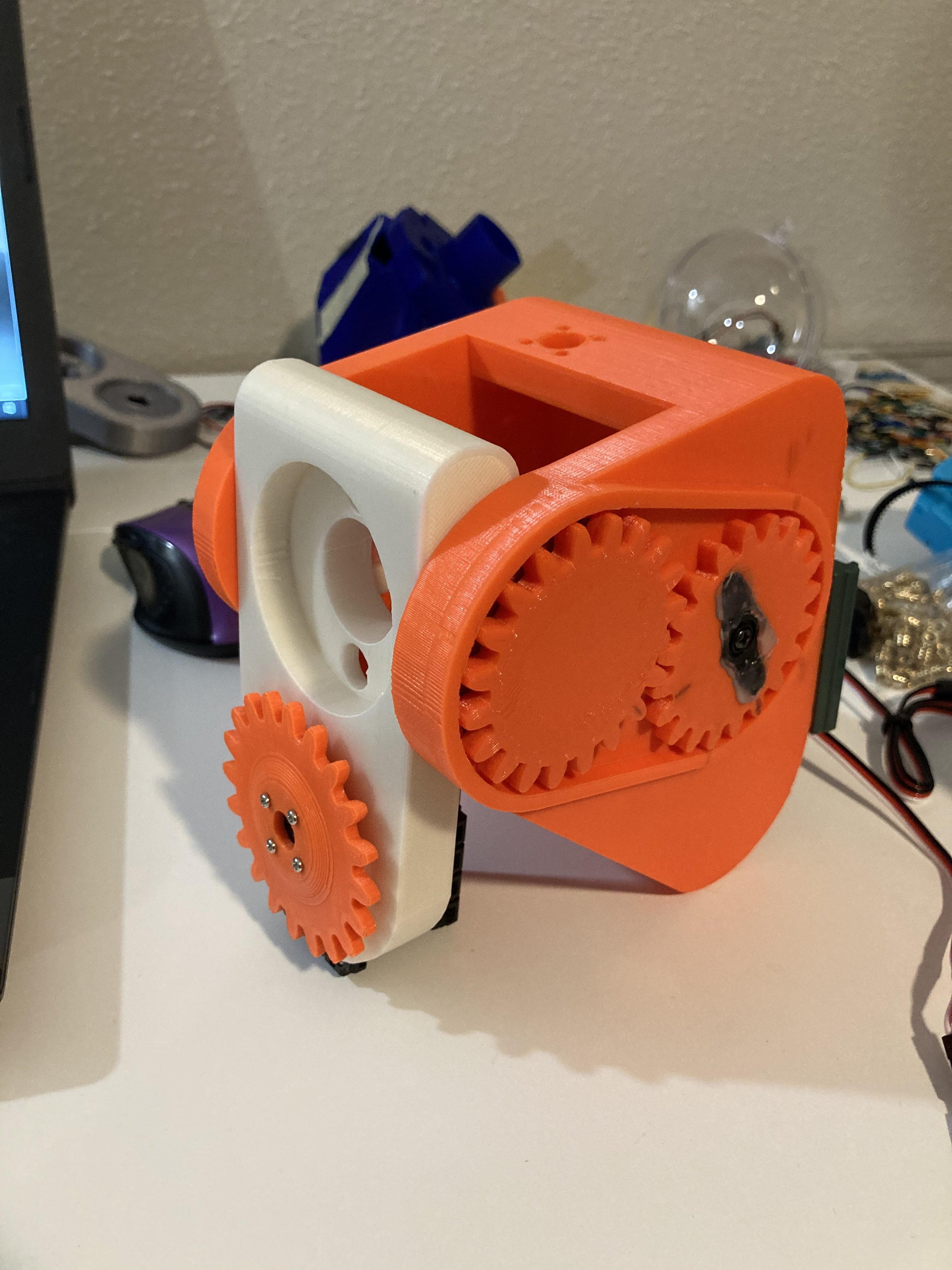
(1) Using that model, I made an early 3DP prototype. I especially liked how the gears came out :)
The cannon sits on a platform (white part), which sits and rotates in a carriage (orange piece). I’ll refer to these components as such for the rest of this writeup.
(2) Physical demo of elevation/azimuth rotation mechanisms! This may be easier to understand than the previous schematic
(3) A ‘shitty robots’ style range-of-motion test, controlled by a Wii Nunchuk!
I could have clamped it to my desk, but it was funnier this way 😆

Then, after I happened to find some spare 2GT pulley parts,
I did a massive redesign of the elevation carriage to use a belt drive instead of gears!
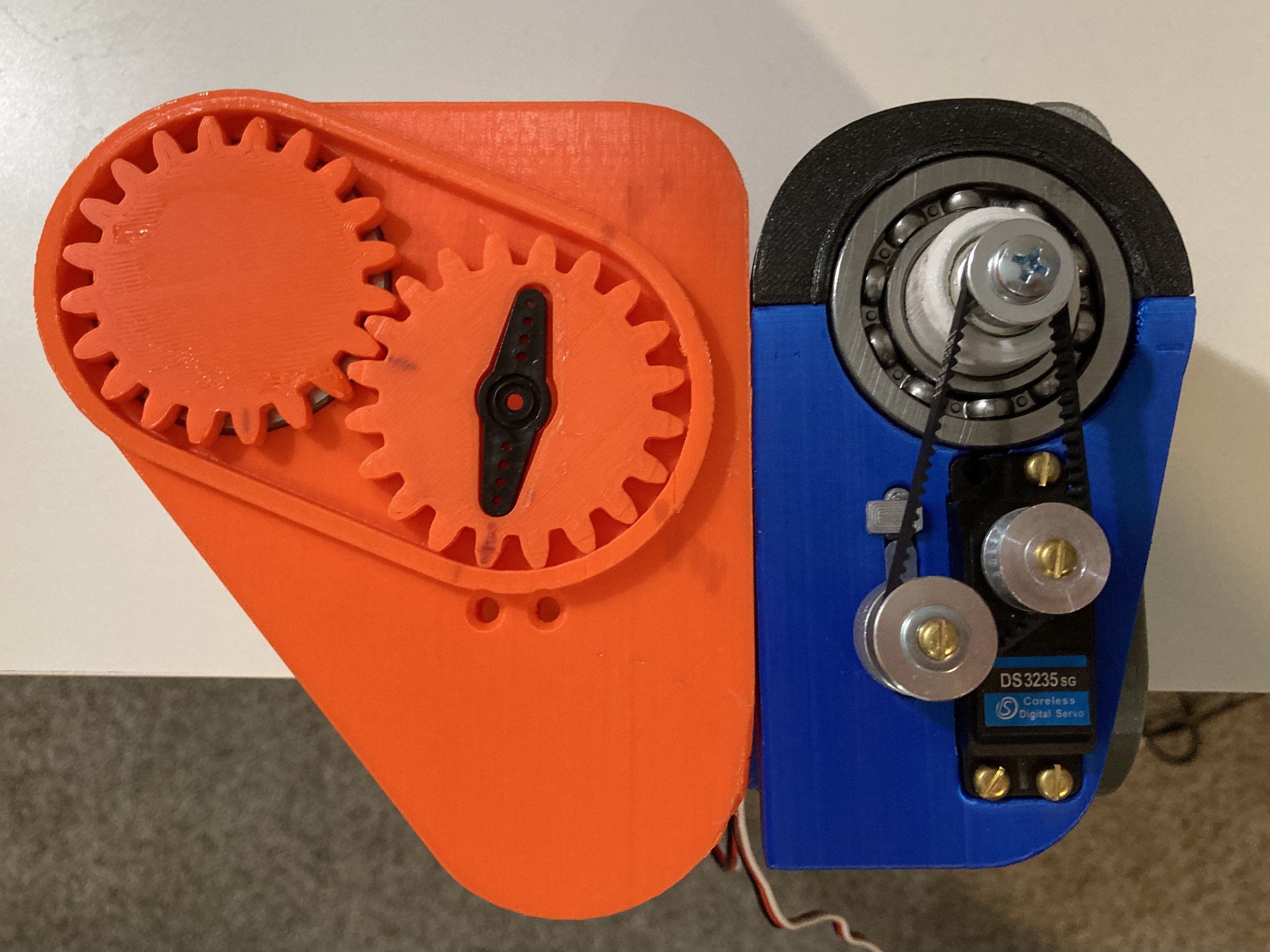
This let me minimize the design considerably. Seriously, the new pulley-based carriage was half the size of the previous geared one!
Initial tests proved promising. I made a variant with a slightly different, wider pulley placement to reduce belt slippage as well.


Something I was proud of and would like to point out:
Look how efficiently I was able to use the interior space, and pack in components super tightly together!
And this immaculate wire routing job too! My effort paid off 🥰
The components circled in green are limit switches that I’ll talk about later, in the Linear Deployment section.

Somewhat anticlimactically, I ended up moving back to gears again. The black and brass look good, though!
My servo wasn’t able to supply the torque to move the full weight of the cannon without the belt slipping and skipping teeth on the pulley, so I redesigned with high face-width gears for lots of engagement area.
As you can see, this ended up working great, even with the full weight of the cannon installed!
Lol at my startled jump - two wires touched and caused it to move when I wasn’t expecting it 😅

The azimuth rotation system was much less problematic, as that servo wouldn’t actually have to fight any gravity.
Pretty much worked on the first try, yay!
Hmm, maybe I should program in user recognition into BAKI, and have it repeatedly slap them in the face if they don’t match my ID signature 😈
Cannon orientation systems (or whatever I called this) — done!
linear deployment

In addition to orienting the cannon vertically and horizontally, I had also mentioned wanting it to retract into a ‘stowed’ state when not in use.
I wasn’t clear on what that meant, so here is a brief demo.
The cannon is stored folded up behind my back, and only when I ‘summon’ it (lol) does it slide up a rail to sit atop my shoulder.
To achieve this vertical linear movement, I decided to use a lead screw and threaded nut! If you’ve ever fidgeted with a nut and screw before, you’ll know that turning the screw while holding the nut still results in relative linear movement between the two.
By attaching a motor to turn the lead screw, you can make an electric push/pull actuator!
This idea is used in 3D printers, with perhaps a more pedestrian example being those adjustable standing desks.
While the lead screw would move my cannon carriage, I still needed a method to keep that motion aligned.
To do this, I bought some linear bearings and some 8mm steel rod. Rip my wallet.
I printed a mounting plate to lock two rod segments in place, making a rail. The bearings are embedded in my cannon carriage, and allow it to slide smoothly on the rods, as you can see!
Everything worked great. Compared to the Dual Rotation stuff, the Linear Deployment system was a piece of cake!
As I mentioned before, I had included quick-release attachments to the Bakugo mount. These allow special hooks to snap in and out, for attaching parts without needing tools.
I mounted some hooks to the rail plate, so that they could be removed quickly, either when I wanted to wear the Bakugo cosplay without the rest of the cannon, or for field repair during nerf battles.
lasers!!

After a classmate I was explaining things to became confused, I thought I’d add this image in.
In both the Dart Zone Scorpion and my own design, the only functional barrel that shot projectiles was the central barrel; the rest were just cosmetic.
However, I thought that was super lame and wanted the other barrels to do some function as well!


After pondering for awhile, I came to the natural solution. I would stick lasers in the barrels!
As a proof of concept, I cut some slots and fitted in the laser diodes. I also drilled a hole in the front for the beam to shine through.
The idea was to have a laser in each of the three barrels, and when they rotated, the lights would trace out a green circle of death on whichever poor individual I target.


When I moved to my redesigned 3DP barrels, I made sure to keep the laser feature as well.
Actually, that’s a bit backwards. The truth was that laser compatibility was the main reason for the redesign in the first place!


But! If we slow down and think for a second, how can we route power from a stationary object to a rotating one? Any wires we attach will get wrapped up around the barrels and break.
The answer to that is — electrical slip rings!
The basic idea is you have a carbon or metal brush that touches the face of the rotating object. Current runs through these brushes into conductive contacts on the rotating body, where a self-contained circuit is located. These contacts are ring-shaped to account for their rotation and wanting to keep a constant radius / distance to the brush.

As I set out to make my own slip rings, I quickly found out — it’s surprisingly difficult to manufacture thin + tall metal rings!
So I shit you not, I dug through my house’s recycling and cut up a green beans can for two nice, easy steel rings. Eat your vegetables, kids


After that, (1) I installed my lasers, (2) used a bit of epoxy to insulate the exposed electronics, and (3) ran the positive and negative leads to their respective slip rings.

Here is the laser tribarrel all powered on!
Quite fitting that I’m shining green lasers out of something made with green bean cans 😂🟢
Seeing the three laser dots arc into circles and signalling certain death would have to wait until final integration testing, but as a standalone element…
Lasers — done!
Electronics - Computer Vision

At this stage, basically all of BAKI’s hardware systems had been developed.
Or at least that’s all I’ve presented so far; in reality I worked on hardware and software concurrently.
In any case — time to cover electronics and software!
The algorithm I designed my original baki turret with was pretty simple. It would:
(1) using OpenCV, analyze incoming video data and ‘mask’ out anything except designated target values
(2) Identify the centroid of this color ‘mass’ and its x- and y- coordinates within the camera’s field of view
(3) Use trigonometry to calculate necessary turret angles, then send corresponding commands to the motors to achieve that.
While that was all well and good…
…The tracking speed ended up being pretty atrocious.
This was probably due to a combination of inefficient code and processor, not the algorithm itself. Real-time computer vision is hard for any computer, let alone a Raspberry Pi.
If I wanted a shoulder cannon that didn’t perform like a joke, I needed to drastically speed up things up.
As I researched and browsed for possible solutions, I stumbled across an entire market of purpose-built computer vision modules.
In addition to having image processing firmware built-in from the very beginning, these also had an optimized camera physically integrated into the chip as well.

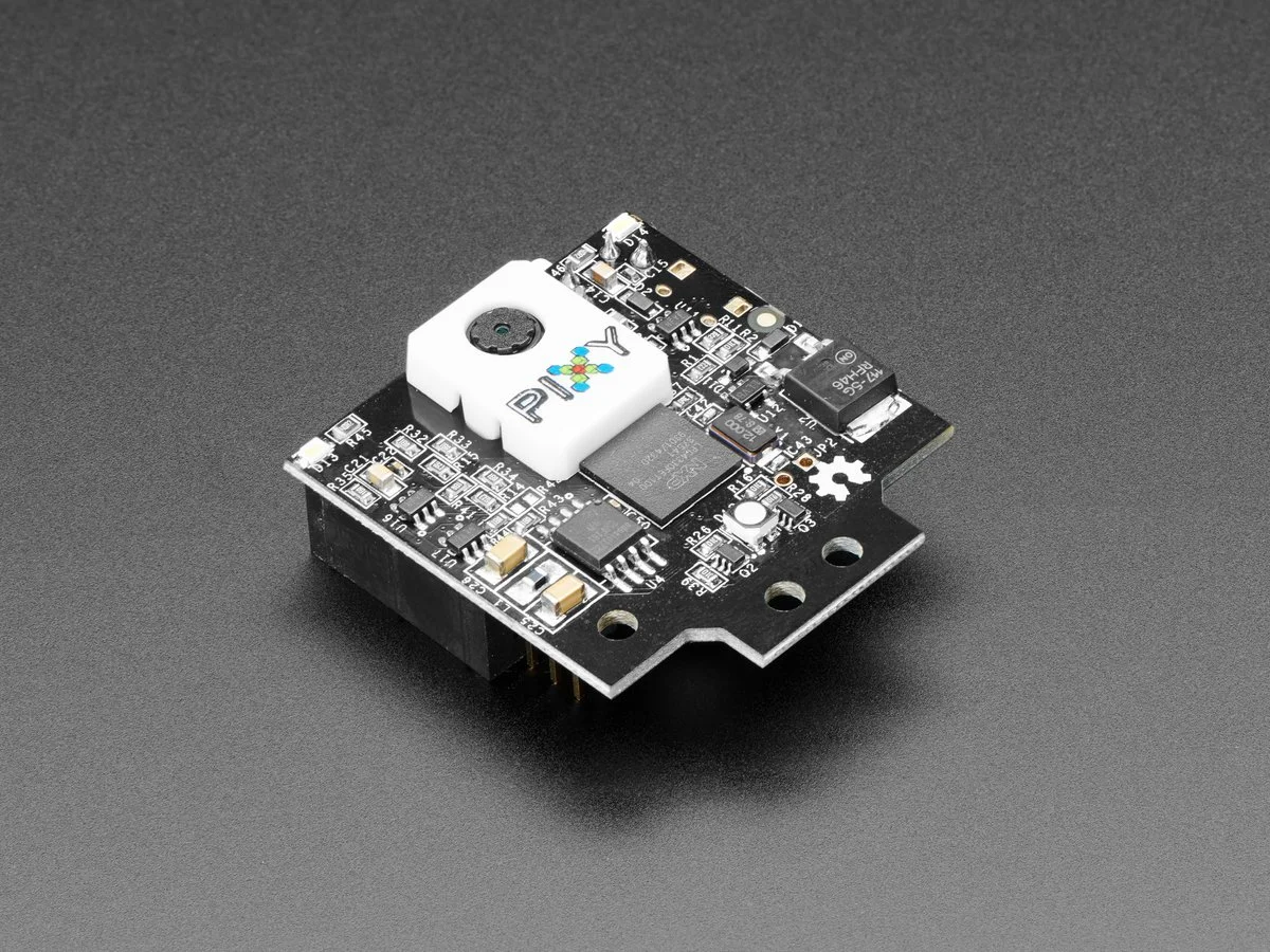
The particular module I chose was the Pixy2 by Charmed Labs. It featured multiple-object recognition and tracking at 60 FPS, which I thought would work perfectly for tracking and blasting my little brothers as they run around at top speed.
The little demo gifs I borrowed from their website left me with super high expectations!

Confirming the Pixy2’s functionality was actually one of my first steps in this project (though presented out of order in this writeup).
Because computer vision was such a critical element in an automatic shoulder cannon, essentially my whole design revolved around it. If the performance was no good, then there’d be no point in continuing.
So after it arrived, I benchmarked its performance by having it track a certain part and commanding a servo to point at it. Essentially a stripped-down proof of concept of how my actual cannon would operate.
With some filtering, I got the system to track super quickly and smoothly (yes, those gifs are its true speed). With this, I greenlit the Pixy2 for use in BAKI!!
electronics - Processor & Management


With the computer vision electronics squared away, I still needed to prepare electronics to control the other systems: mode select / user interface, motor math, motor commands, power management, communications, etc.
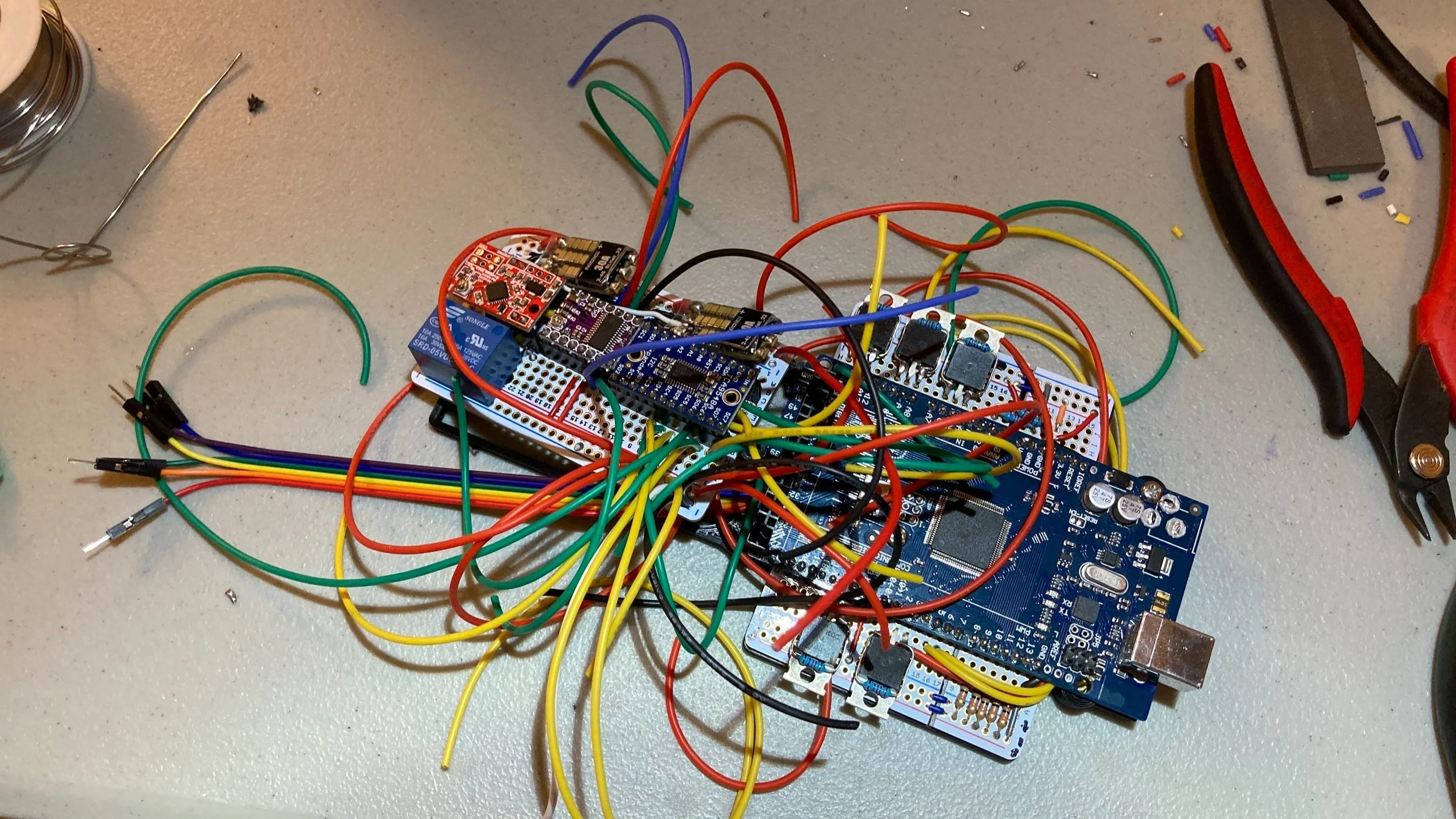
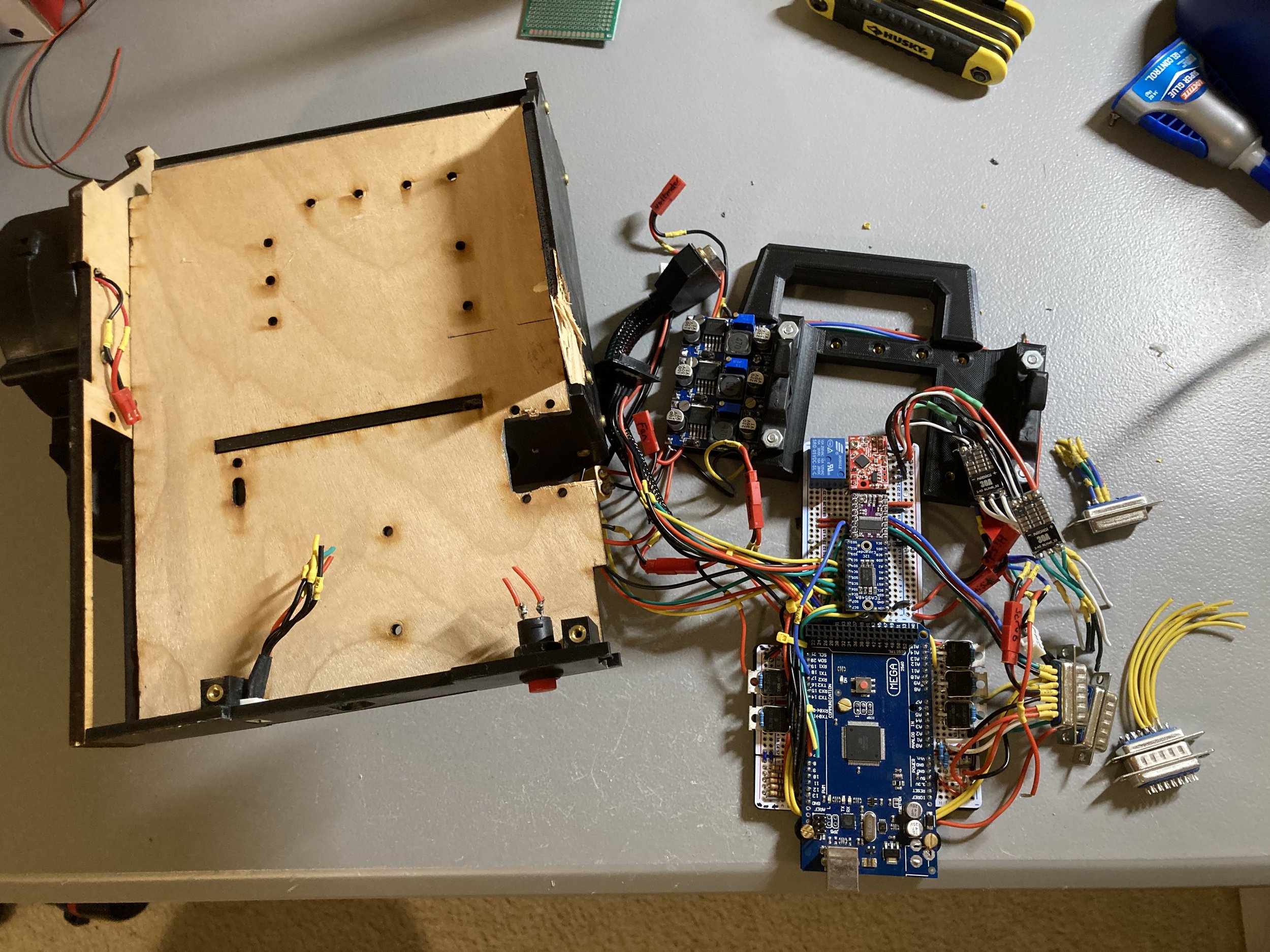
Most of these functions would be handled by an Arduino Mega microcontroller (the big blue board), with motor control and other tasks outsourced to various smaller boards. The white boards are protoboard - basically provides an anchor and makes connections easier.
Once I had determined all the electronics I would need, I basically played Tetris with them, mockup up different arrangements until I found one I liked. Then I threw everything into Solidworks for documentation.
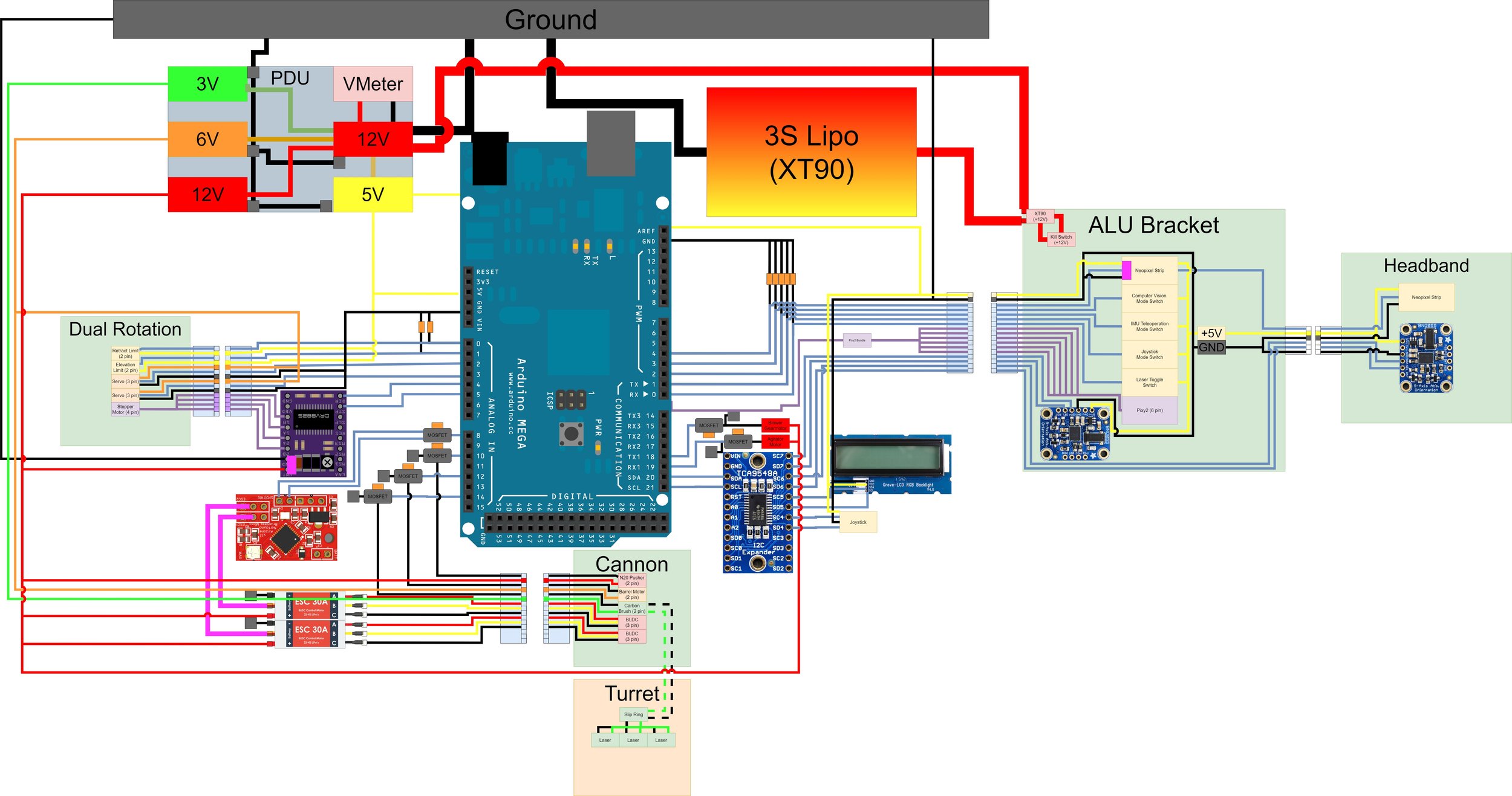

I sat down one weekend and planned out how all the different electronics needed to be connected. Power, ground, signal, clock, etc.
I started out using diagram-making software, but eventually decided marking up pictures was more helpful for visualizing actual wire routing. I had recently bought a drawing tablet, so that made this much easier than you might think.
Using these drawings, I hand-wired every single connection. This on the other hand was much harder than you might think.

Despite my demonstrated penchant for self-inflicted punishment, my choice to hand-wire everything on protoboard, as opposed to making a PCB (printed circuit board) wasn’t one of them.
The truth was that I simply didn’t know any other method. Due to the simplicity of all my prior projects, I’d been able to get away with it.
But having to measure, cut, strip, twist, solder, and heatshrink the hundreds of connections in this project really sucked, and took me an entire holiday break (plus my sanity).

But I managed to finish! I tested all my connections with a multimeter and confirmed I hadn’t made any mistakes.
Finally, I used zip ties to (somewhat) organize the wirepaths, threw on an acrylic window to both protect/showcase everything, and declared electronics complete!
integration + Test


Now with physically 100% complete cannon (mechanisms and electronics), it was time to integrate and test everything as a single unit!

My brother helped me write out some code…
And we began testing — first individual systems, then various combinations of systems. Just building things up in steps, changing one variable at a time. You know how it be.
BUT…
(yup this is where the other shoe drops 😢)…
Though things seemed to be working initially, when we reached final integration testing, with all 9 motors connected and running, BAKI would ‘brown out’ and lose power, force-reset, & repeat. This had been my worst fear on this project, and it had just come true.

Despairing, I dived back in and went looking for the mistake using a multimeter.
I had to check three times (it’s a lot easier to find an error than prove there is none), before confirming everything was correct. I concluded that the problem must not have been no connection, but not enough connection.
Meaning, the components I chose couldn’t let enough current through to adequately ‘feed’ everything. I think the biggest culprit here was the protoboards. My power calculations showed that BAKI would draw up to 84 amps at full power, and no way could all of that current make it through those tiny traces that you can see.
Facing the fact that I’d have to redo the entire electrical with higher current-carrying components, I cut the loom out of the backpack unit. F’s in the chat boyes 😢
PCB

While I had initially avoided PCB design to not delay the project in running off to learn a new skill,
I decided that with the project now delayed either way, and having a high-current PCB realistically being the only way forward, I’d do it.
Conveniently, one of my powerlifting buddies, Fredy, was an electrical engineer, and he helped me learn the PCB design software EAGLE!
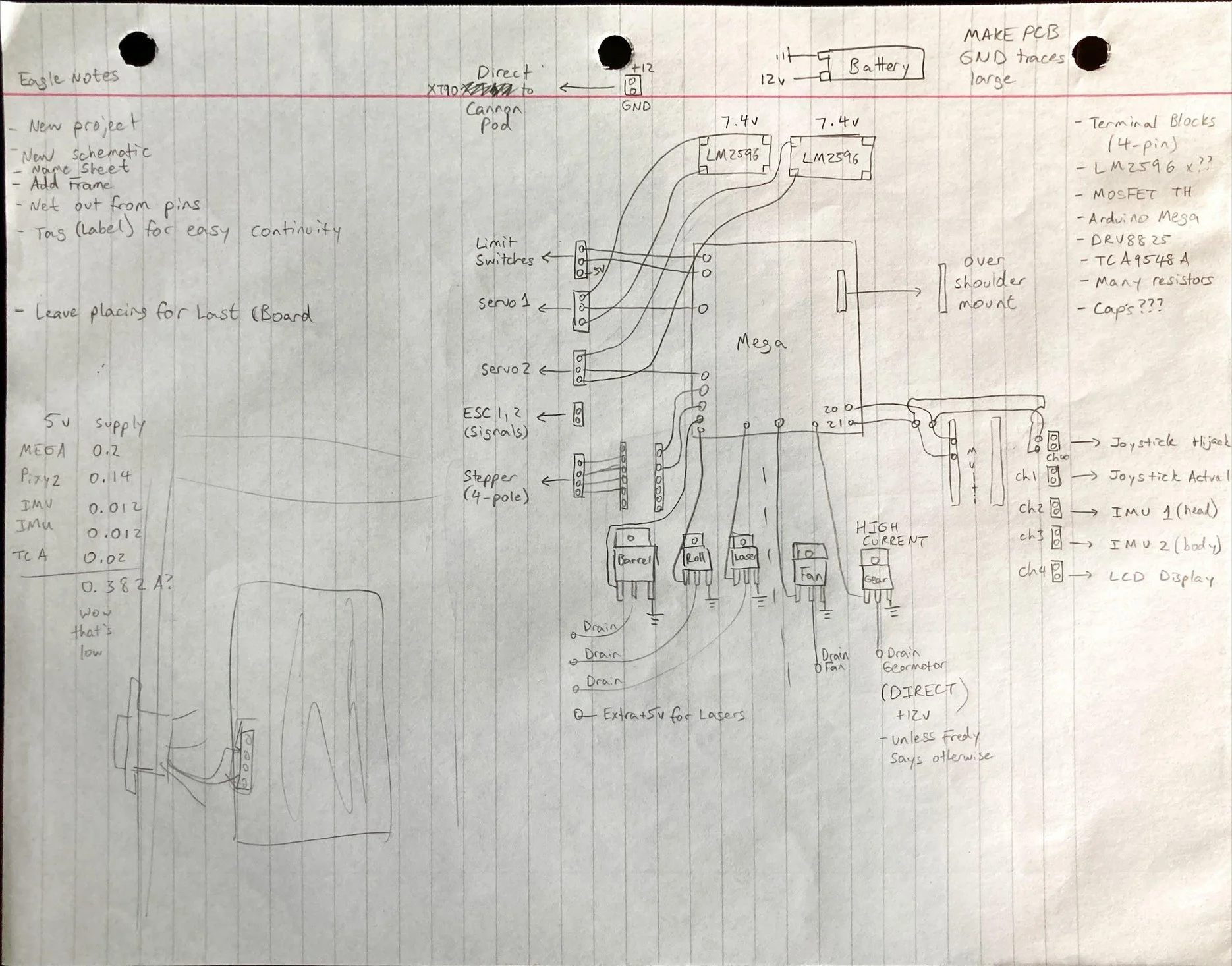

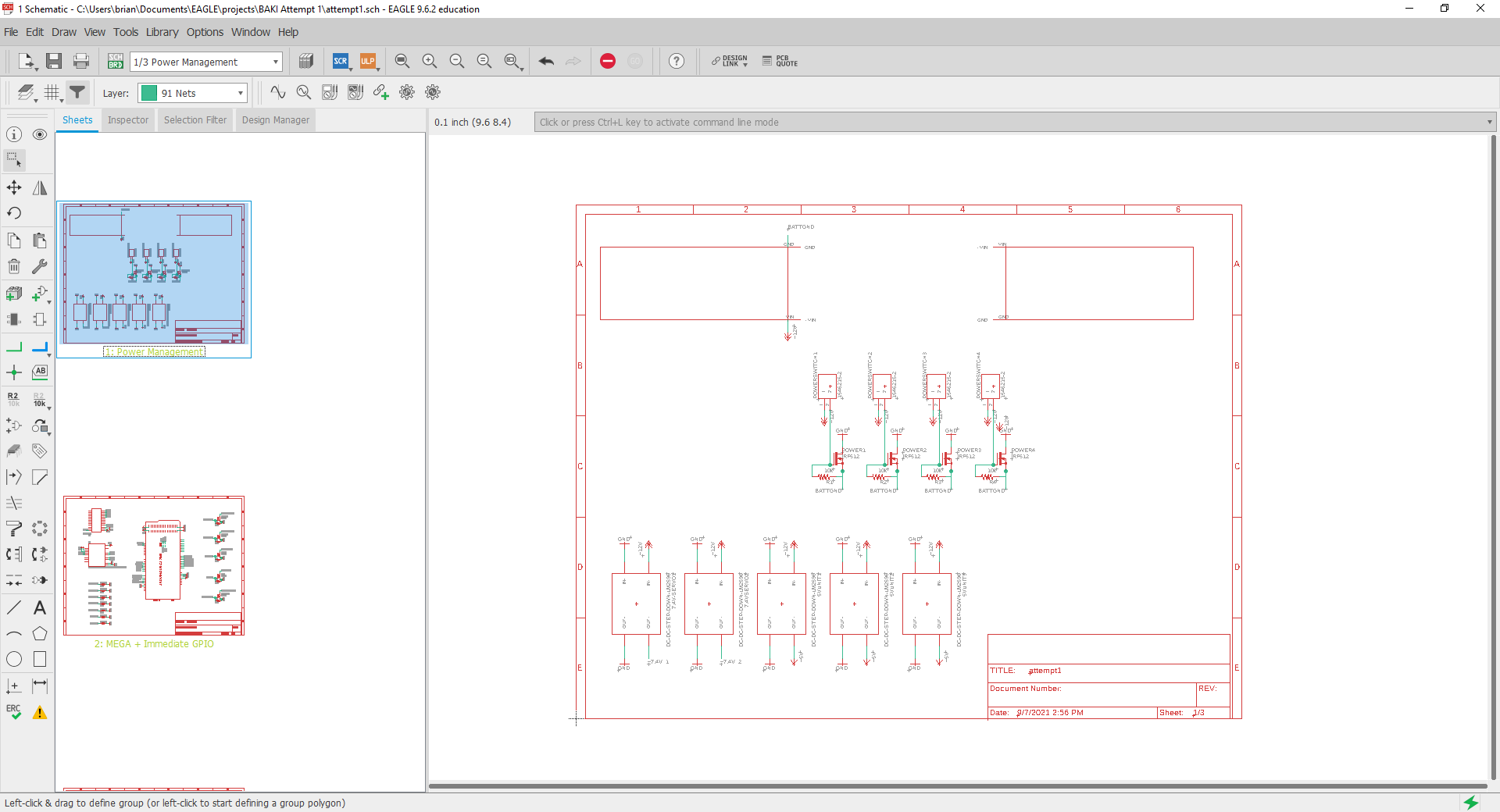
Because I had already made the circuit once by hand, it was easy to redraw it from scratch in an EAGLE-friendly format
From my pencil sketch, I transferred all the elements into EAGLE Schematic, one of two main workspaces within the software
In Schematic, you are just assigning connections between different pins. Just detailing Point A’s and Point B’s, without worrying about the paths between them yet.

The other workspace, Board, is where you plan the physical placement of your electrical components on the fiberglass PCB body.
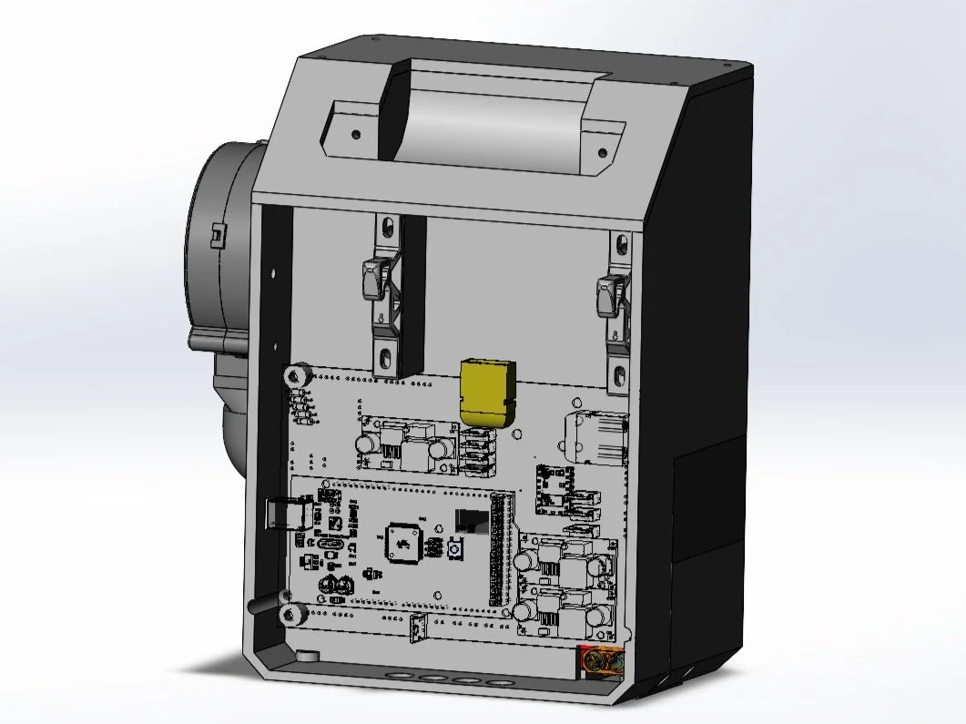
(1) My process was to first inventory all of the electronics I needed,
(2) Plan out the spacings in CAD to see what the biggest board I could fit in the backpack was,
(3) then come back and place the electronics footprints in their respective homes in Board

The next step within Board is to route your traces - basically playing connect the dots with copper connections, where the dots are all the Points A and B you set earlier in Schematic. This goes without saying, but the having copper between nodes is what actually lets electricity to conduct through them.
EAGLE has an Autorouter that more often than not gives you suboptimal wirepaths, but it does lend for some cool aesthetic gifs!
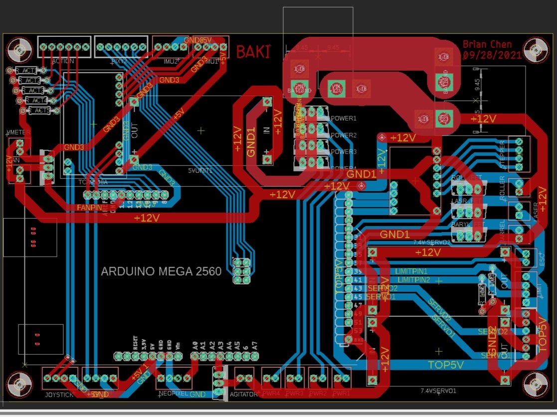
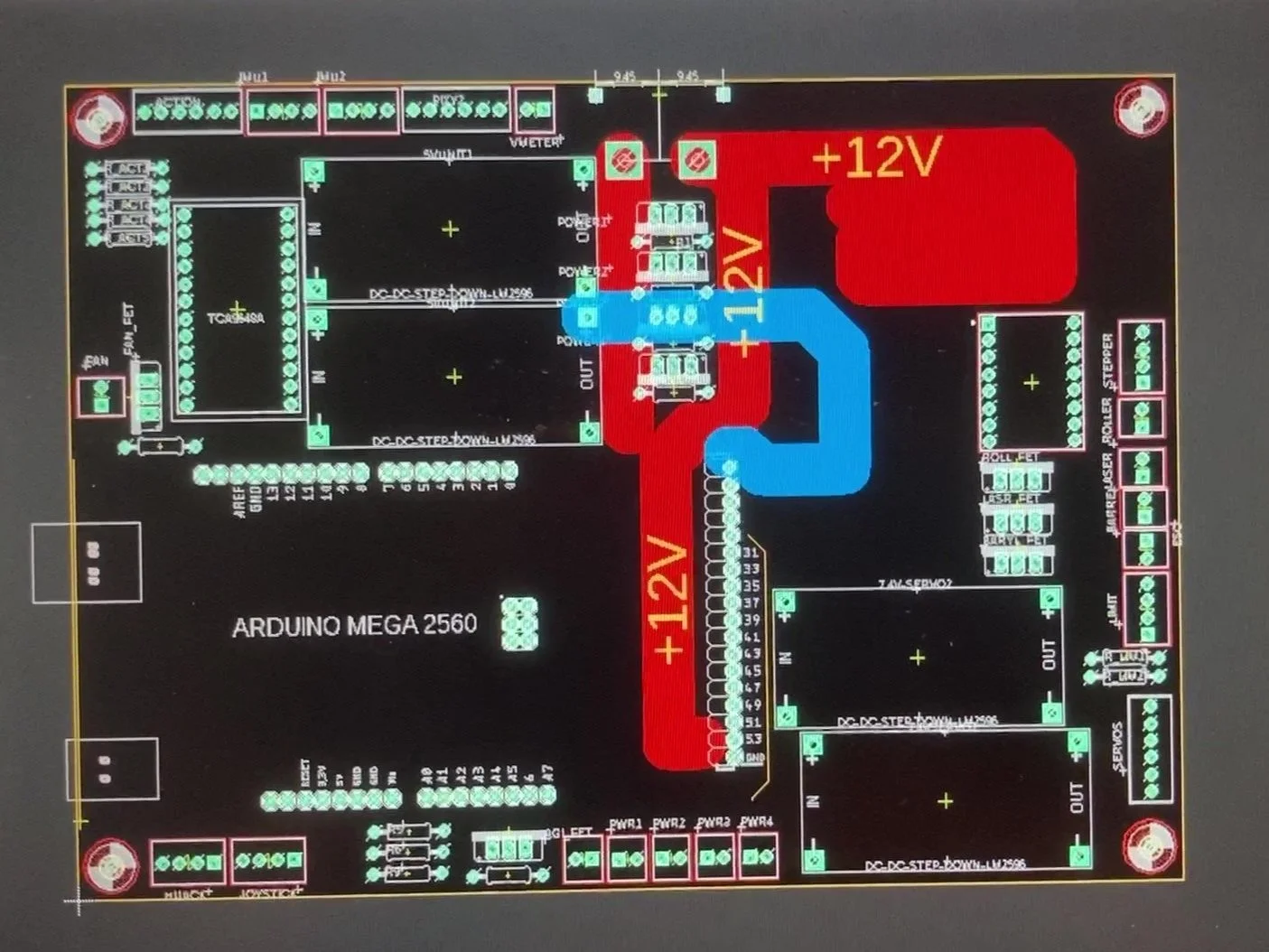
It took a while, but I routed all of my wires by hand, leaving the traces nice and thick for lots of current to flow through.
Some of my traces were 13mm thick (for those without context, that’s a lot!) The red lines represent copper on the PCB’s top face, and blue represents copper on the board’s bottom face.
I had this design looked over by a few Elec friends (thanks, James, Fasai, Fredy!! 🥰), before sending it off to the JLCPCB factory for manufacturing.

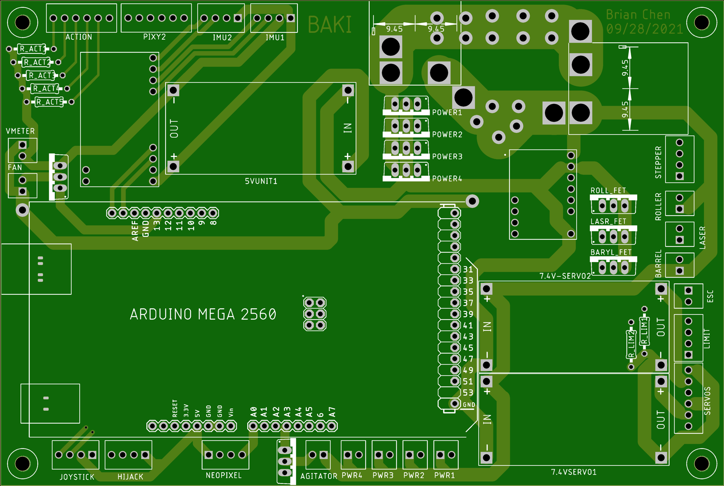
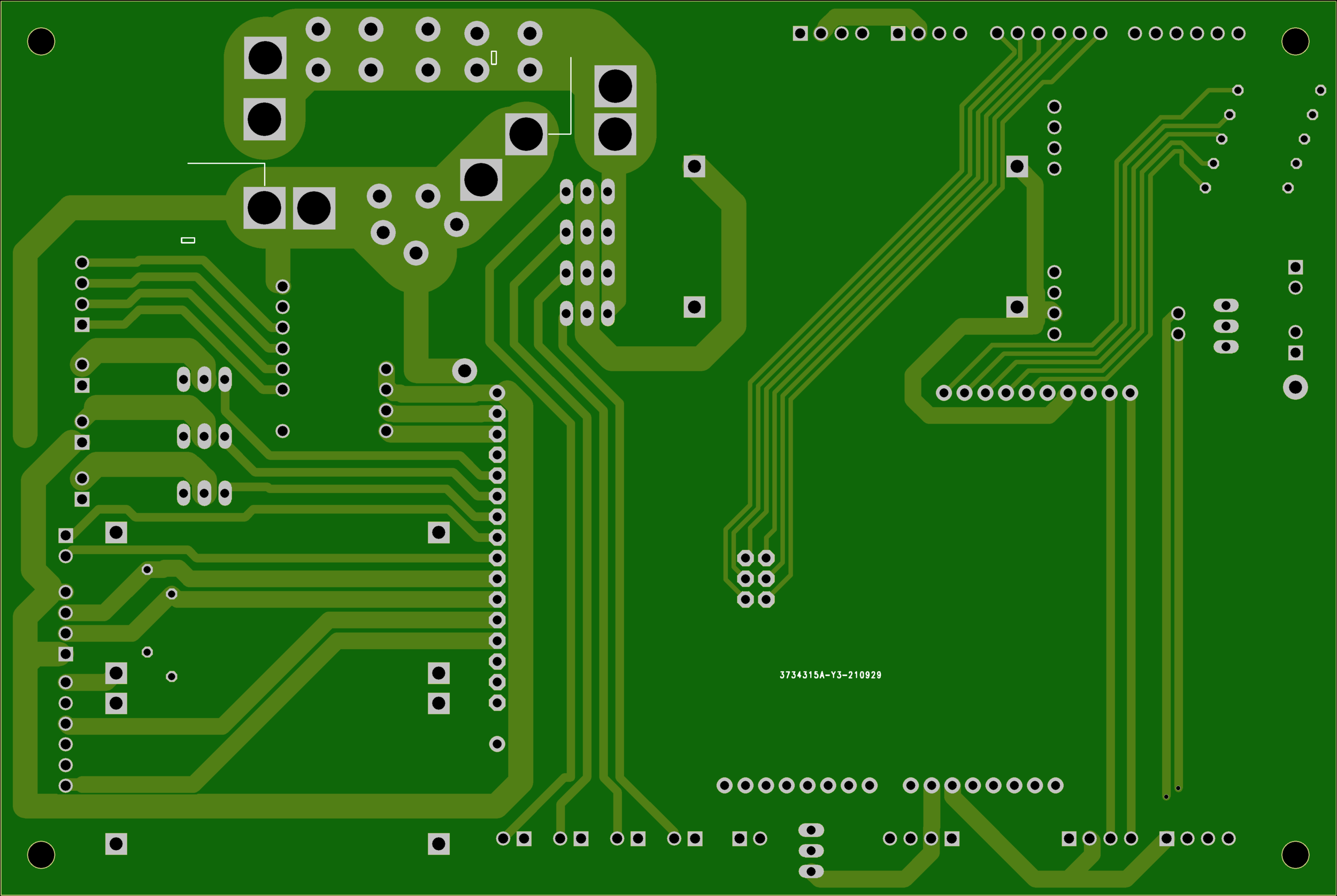
In the meantime, I spent way too much time making a 3D model of my board. I was bored!
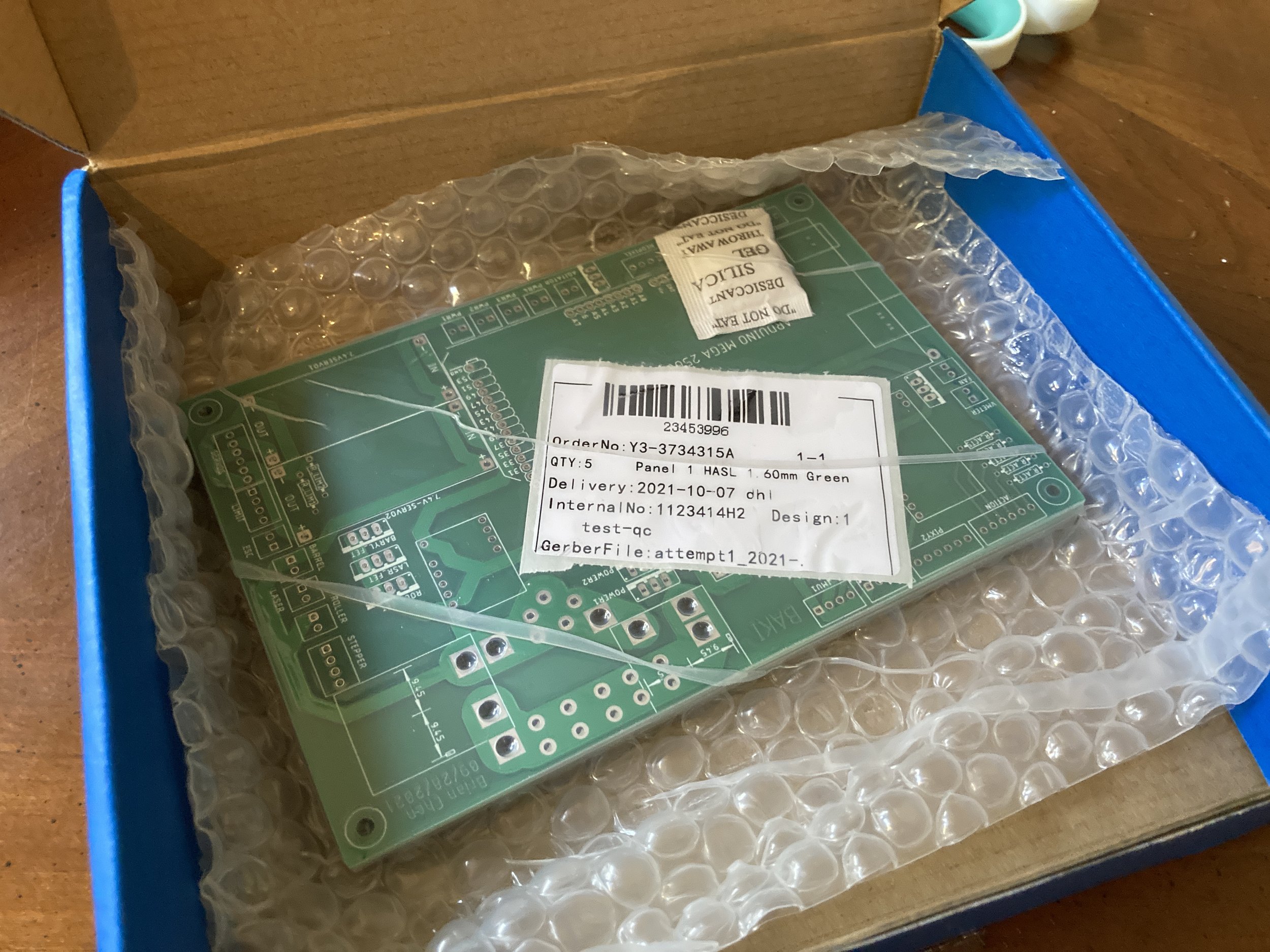


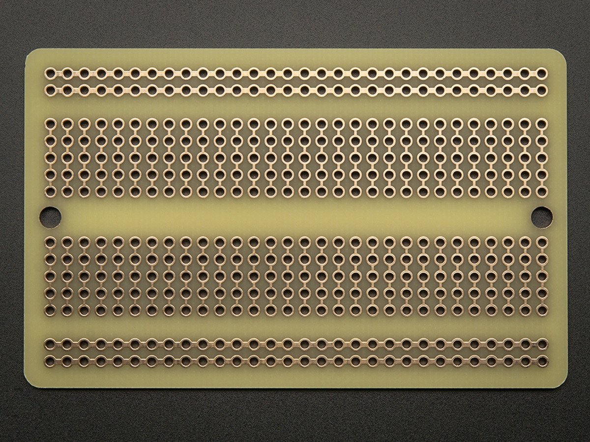
One week-ish later, my PCB blanks arrived! WHOAAAAA!!!!!!!
It was honestly super cool to open the box and see a design I’d spent weeks on, come back in fresh green fiberglass. I think because I typically fabricate all my parts by myself, seeing their every step means there is no surprise at the end. But because these were boards someone else made for me, it was like opening a present 🎁🧧 and really made my day!
(I also wrote my name and the BAKI project name on the board, also super satisfying to see 😎)

I sat down, plugged in all of my electronics, and soldered them in. This took a few hours as opposed to a few days with my handmade board, so I was very thankful. In addition to ability to add high current tracing, PCBs are also much better for high volume / mass production 🤔
It looks so legit! And when I power tested it, everything worked, meaning that I had designed in EAGLE correctly.


Here is the old board v.s. the new — what an improvement! Fredy told me that it’s actually super impressive that I got PCB design right on my first try, so I got a bit full of myself and made the Vegeta meme on the right 🤣
one final effort
And that’s about the current state of the BAKI shoulder cannon! There is just a bit of work to do left (install electronics, test, document, etc.) but I’ve put the project on hold temporarily as I try to find a job. Component costs were getting too high for self-funding, and y’know, trying to be a generally responsible adult 😜
If you’d like to support the build, and happen to be an engineering recruiter or manager, well - HINT HINT 👀
Otherwise, I hope you enjoyed! Hopefully you learned something, or recognized some of my anime references. Maybe stick around for when this gets updated/completed, or check out some other projects?
Thank you for reading!!