
RICE ELECTRIC VEHICLe

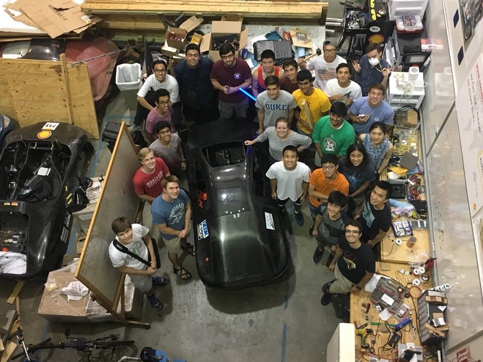
Rice Electric Vehicle has been a huge part of my undergrad life. I joined the team in my first semester at university, and never looked back.
We worked together to design and build electric cars to race in Shell’s Eco-Marathon, an efficiency-focused competition aimed at tackling the energy challenges of our near future.
In my time with the team, I’ve gone through multiple EV design cycles, learned a ton of skills, and most importantly, had a great time doing it!
Sometimes I myself forget, and have to remind myself of just how cool the stuff we worked on was — We built an honest-to-goodness running CAR! 😮

At the time I joined REV, many seniors had just graduated, taking their experience with them without properly documenting it for posterity.
Our team was almost exclusively incoming freshmen, and together we spent our first year trying to re-learn knowledge that had been forgotten.
I think a big theme throughout my time with REV was inheritance: trying to learn from our predecessors’ successes and improve upon their failures.
A REV-ival, if you will 😂
Finally, a heads up: this will be a massive writeup due to the literal 5 years of content I’ll be talking about!
So if you’re here for a good time but not necessarily a long time, consider skipping to and just reading the Powertrain section!
It serves as a great thematic & technical vertical slice of my work at Rice Electric Vehicle, and I’m really proud of it!

Otherwise, for your sanity as well as my own, I’ve organized everything into sections:
carbon fiber body construction

Though we hadn’t been left with much formal documentation, we were fortunate that last-gen Rice Electric Vehicles had been left abandoned in our club workspace for us to reverse engineer from.

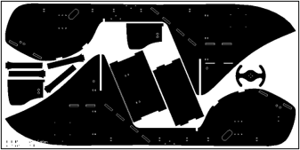
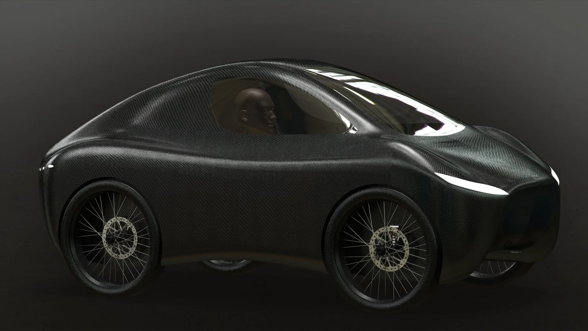
While trawling through old archives, we found schematics for the existing car bodies. Someone years ago had created this model, and verified its aerodynamics using computational fluid dynamics (CFD).
It featured a unibody monocoque design, meaning that the body and frame were a single, integrated piece. This would help reduce weight and thereby increase energy efficiency.
With those considerations in mind, and really for lack of any other direction, we decided to replicate this design! 😅
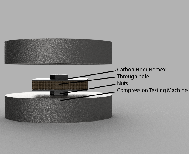
Previous cars had been constructed using 1/2” panels of composite carbon fiber and a Nomex honeycomb material, that allowed for most of the rigidity of a pure carbon fiber panel of that same thickness, at a fraction of the cost.
We found schematics for interlocking panels that slotted into one another, so with the school machinist’s help, we got them CNC milled out and assembled! We used additional carbon fiber weave and resin on the joints to reinforce them.
This would be the inner ‘frame’ of the car, and later attached to the body to achieve the monocoque I mentioned earlier.
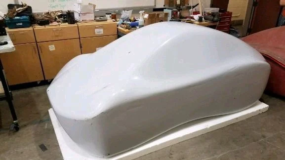
Next, to create the body itself, we used more existing parts.
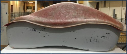
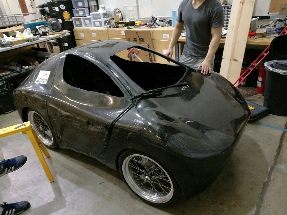
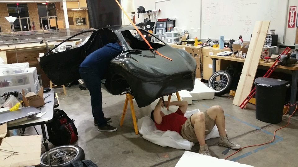
The 3D model for the car was sent out to have sculpted into a positive, or plug (the white car shape), after which two negative fiberglass molds (the brown piece) were formed around it, like a clamshell!
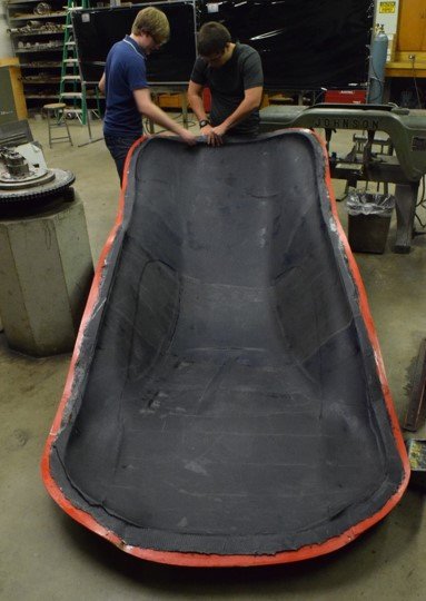


We draped layers of carbon fiber weave on the inside of these the molds, soaked resin into them, and used vacuum bags to squeeze them together as things cured and set. Using this technique, we produced an upper and lower half of the car shell.
We trimmed away the flashing, placed the frame inside, and permanently bonded the two together using carbon fiber. The whole process is very similar to making pinatas from paper mache, except you’re using CF and resin instead of paper and glue.
Finally, we cut out holes for our windows! (and eventually the door, trunk, and wheel wells too).
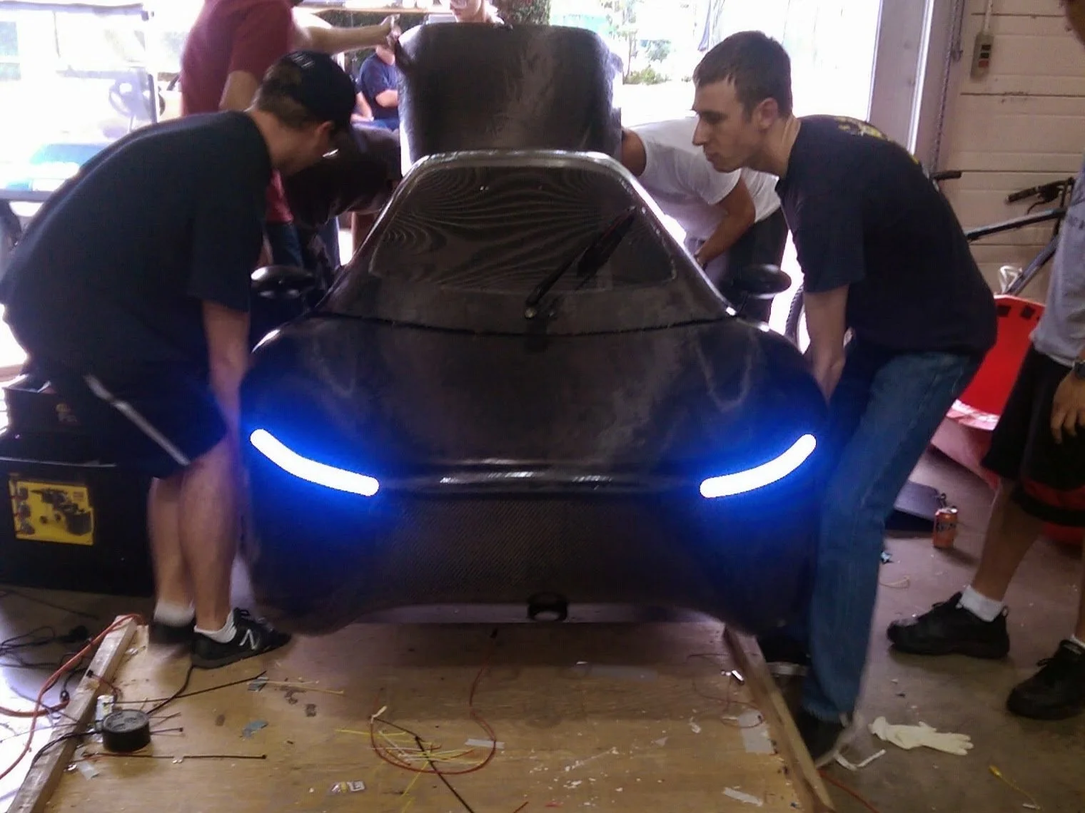
Thus, we finished the body of our 1st EV! We named her REVolution.
Both for the pun, and the fact that all this new blood was a literal revolution, or like a ‘changing of the guard’.
Rear Drive wheel Mounts
Next, to make the car a roller, we needed to mount wheels!
Due to us all being so inexperienced in auto design, we decided on go-kart style…
Meaning no shocks, no dampers, no suspension system — instead relying on body rigidity to absorb shock.
(Something he monocoque body was very conducive to)


We decided to start with the rear drive wheels, as there was no complicated steering to think about yet.
During a teardown of a previous REV, we found that our predecessors had used a suspension-less rear wheel mount as well, so we felt validated in our decision as an acceptable one.
They had mounted a rectangular aluminum tube with bearing-studded caps to hold offset wheel shafts.
The previous wheel mount, however, had visible damage and deformation, indicating that we should probably redesign. To make an improved version, I went and taught myself Solidworks, a powerful 3D modelling tool.
I modelled a wheel mount design that was similar to the previous one, but with key differences:
(1) Instead of the wheel shaft sitting offset and exterior to the aluminum box tube, I moved it to the tube interior, in hopes of symmetry reducing weird reaction moments.
(2) I moved the bearings to the tube interior to protect against potential external damage, and added a brake mount as well.
It’s pretty rudimentary, but I’m still proud of freshman me for getting that far. For some reason, Rice doesn’t even require a 3D modelling course for their Mechanical Engineering degree, so in that sense I was way ahead of my class!
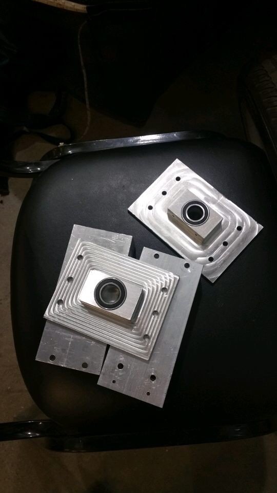
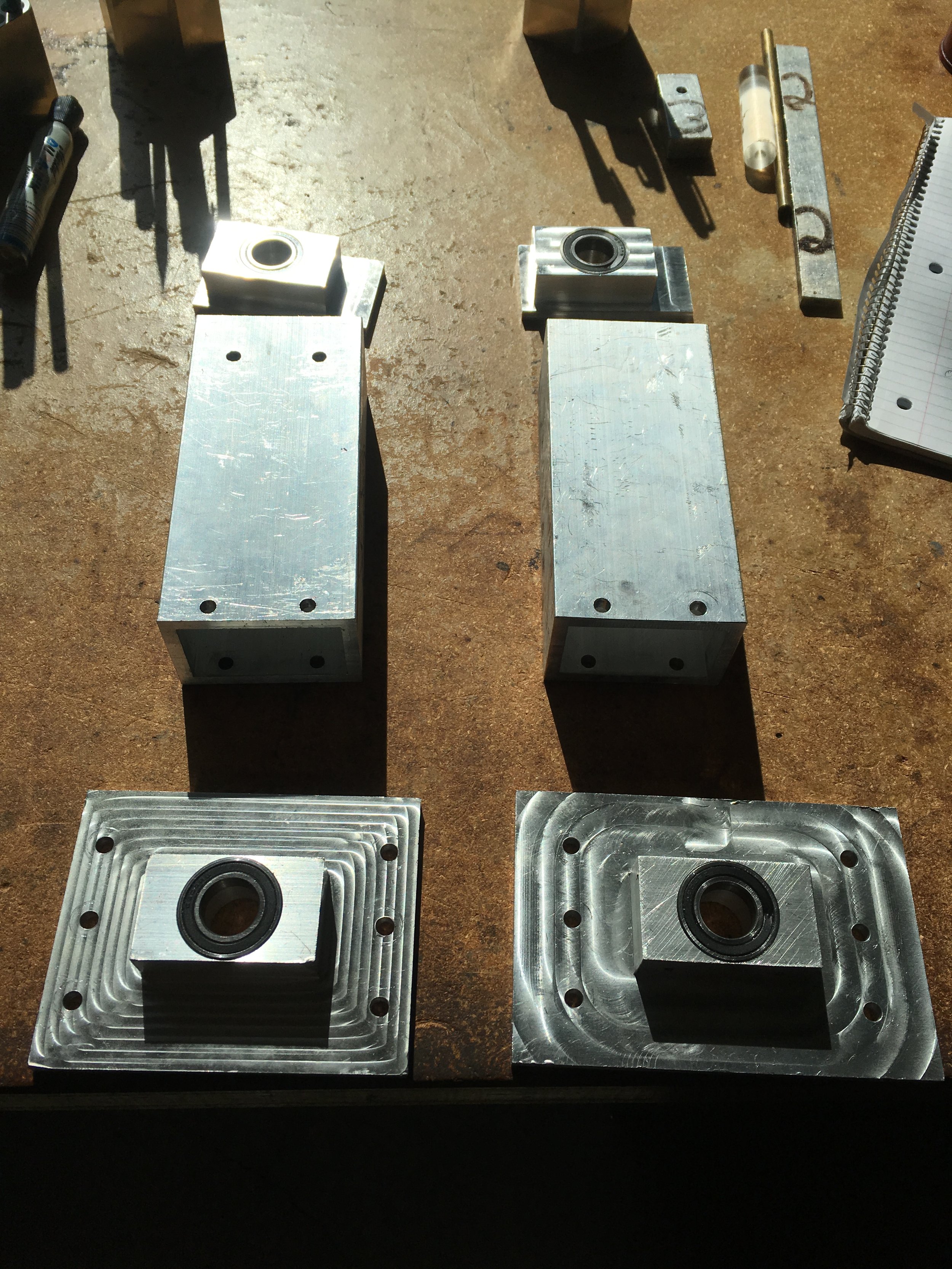
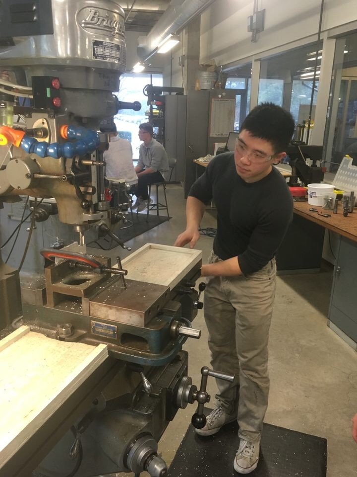
I went to Joe the machinist, and we worked together to mill the parts out of 6061 aluminum.
Since I hate creating waste, my new design actually used materials from the old one! I was able to salvage all 4 bearings, as well as the rectangular aluminum tubes, saving some money and keeping stuff out of landfills!
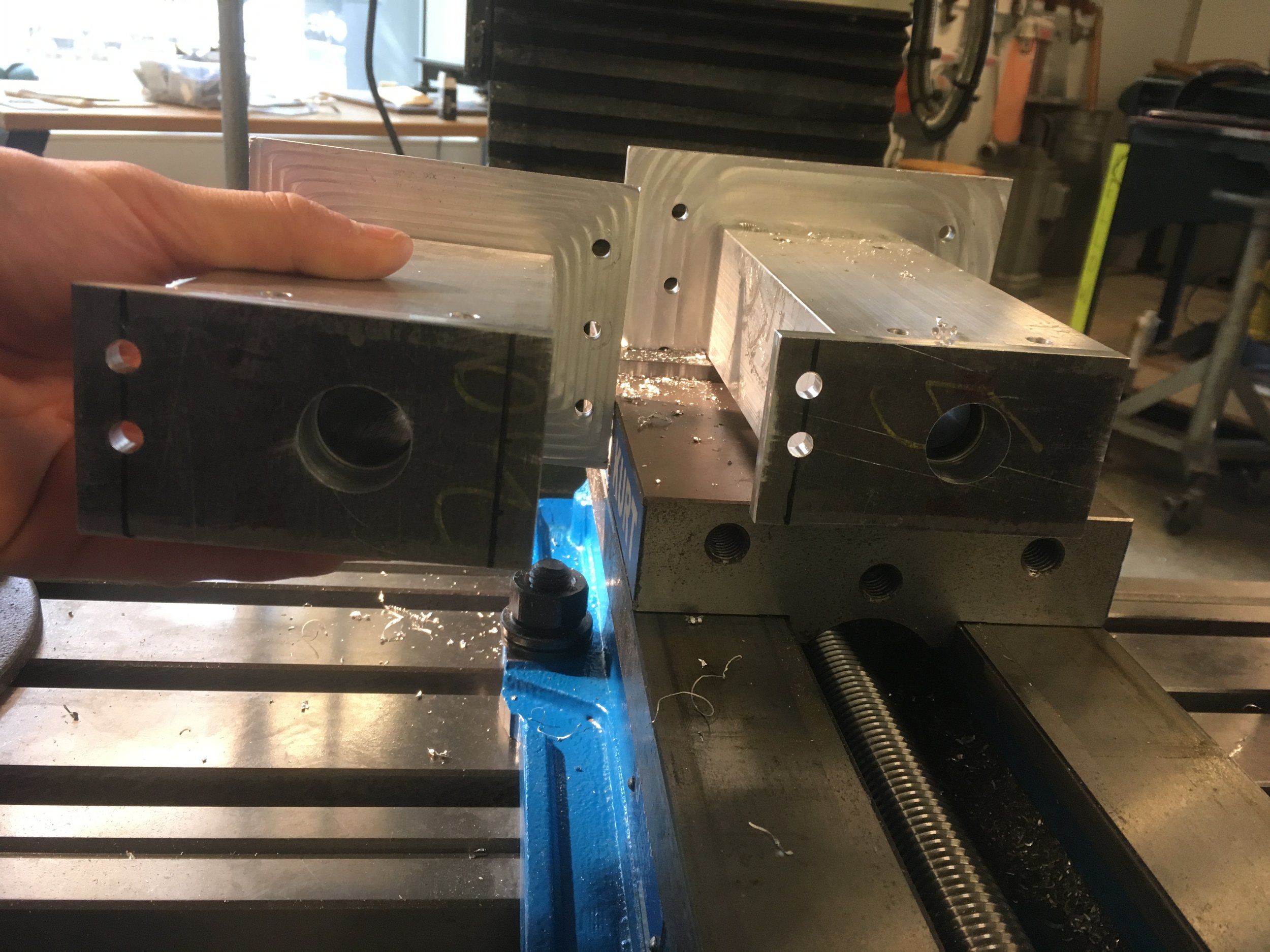
After we machined everything, I pressed bearings into their pockets, and pressed both end caps and box tube together.


TA-DAH~~~!!! Brian’s first bona-fide machined part, complete! 😤
wheel Hub adapters

While having our shafts mounted was nice for sure, it was still only a bare metal shaft!
Now, we needed a method to securely mount the wheels to that shaft!

A plan was planned.
We would screw an inner cap into the wheel hub, then thread it into the wheel shaft.
Then, a second outer cap would bolt into the inner cap, clamping onto the wheel hub from both sides, rather than a single face.

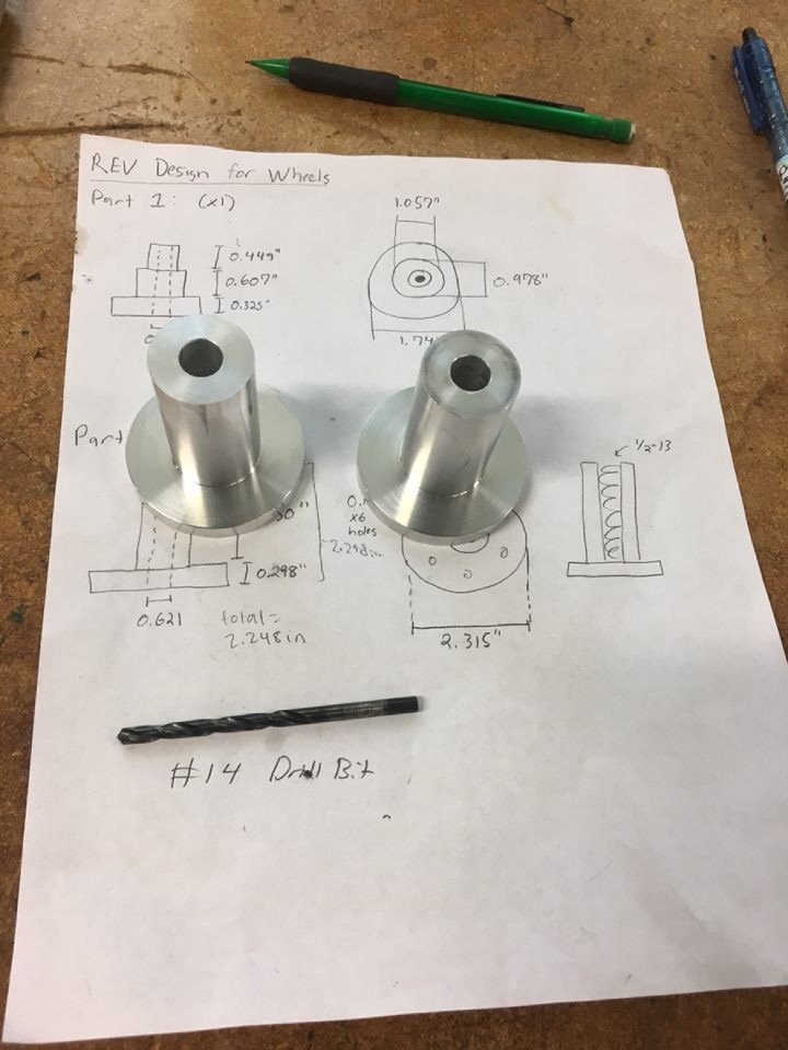
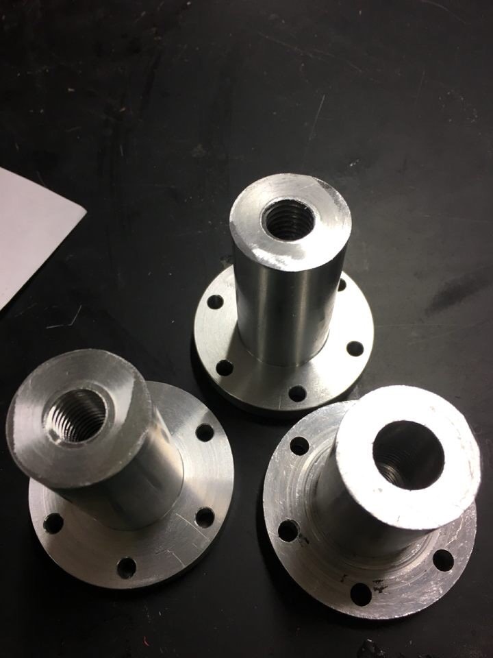
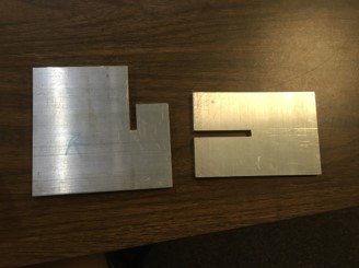
Threw some CAD drawings together, then got these inner caps cut and threaded on the school lathes.
The six holes are for us to bolt into the wheels, and the threading visible on the bottom left piece is for the bolt to tighten and clamp the outer end cap on, as mentioned.


Here is the inner cap bolted into a wheel. The design also allows a disc brake to be clamped in between itself and the wheel.


After that, we cut some threads the shaft, then used a segment of threaded rod to tighten the inner end cap onto it.
We used tension pins were used to prevent them from ever separating.
Finally, everything was plugged back inside the suspension! Things are coming together!

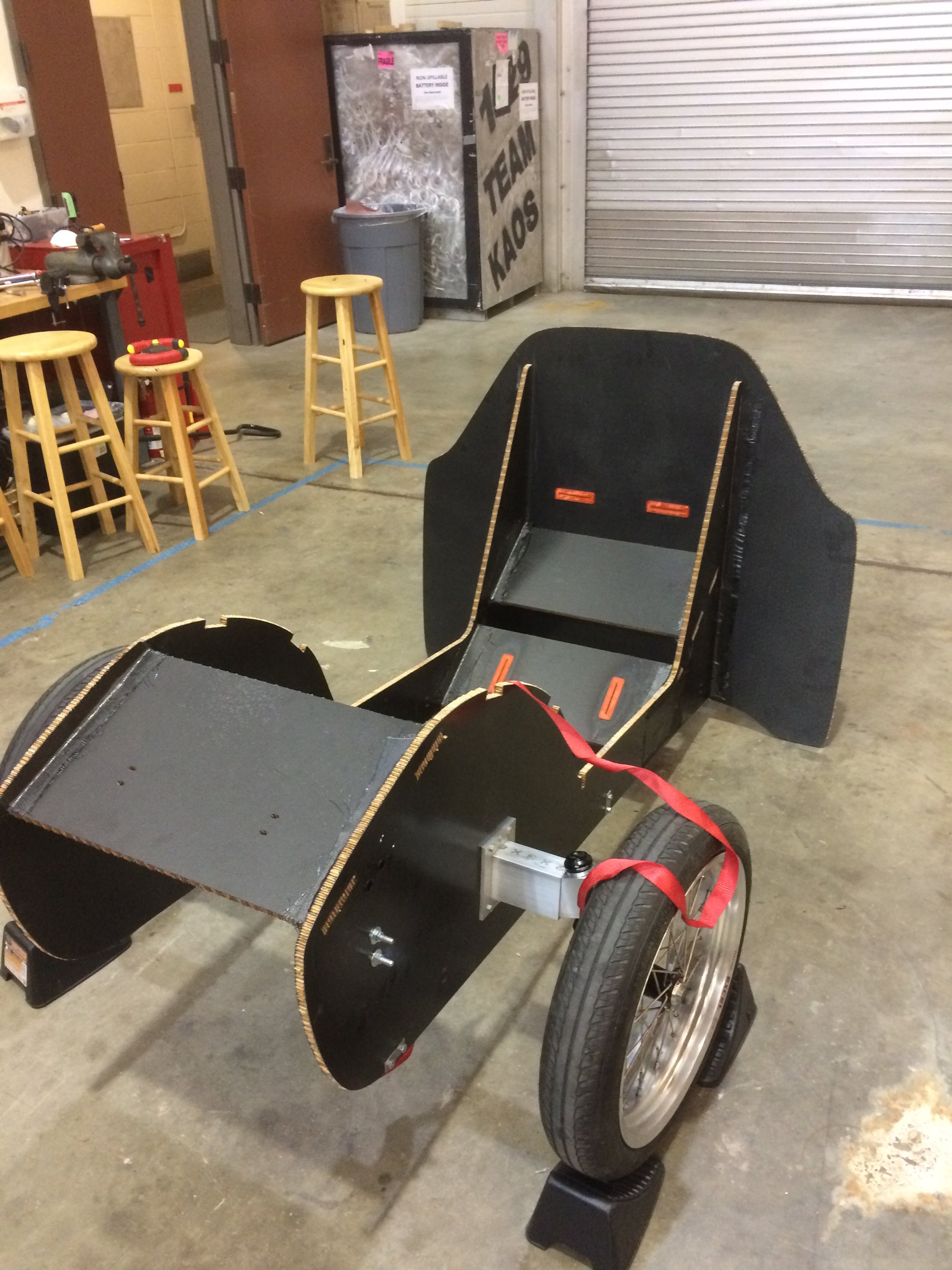
Guys! We did it!! We got the car on 4 wheels!!!1!
At this point the car could freewheel — which would be perfectly fine for a downhill course — but that wasn’t enough.
Next, we add POWER!!
powertrain


Our next step towards a drivable car was to add the powertrain - basically all the moving elements to bring power from the motors to the wheels.
We looked into the previous cars for ideas, and found, well… not much. A mess of wires and notably, a single-motor setup in the trunk. (Our cars used a rear ‘engine’, rear wheel drive layout)
My buddy Marco and I formed a mini task force to redesign a more robust powertrain system. (Still as freshmen!)
First, we had to determine what went wrong on the previous team’s design, to better create our own.
(Basically an after-the-fact DFMEA session 😅)
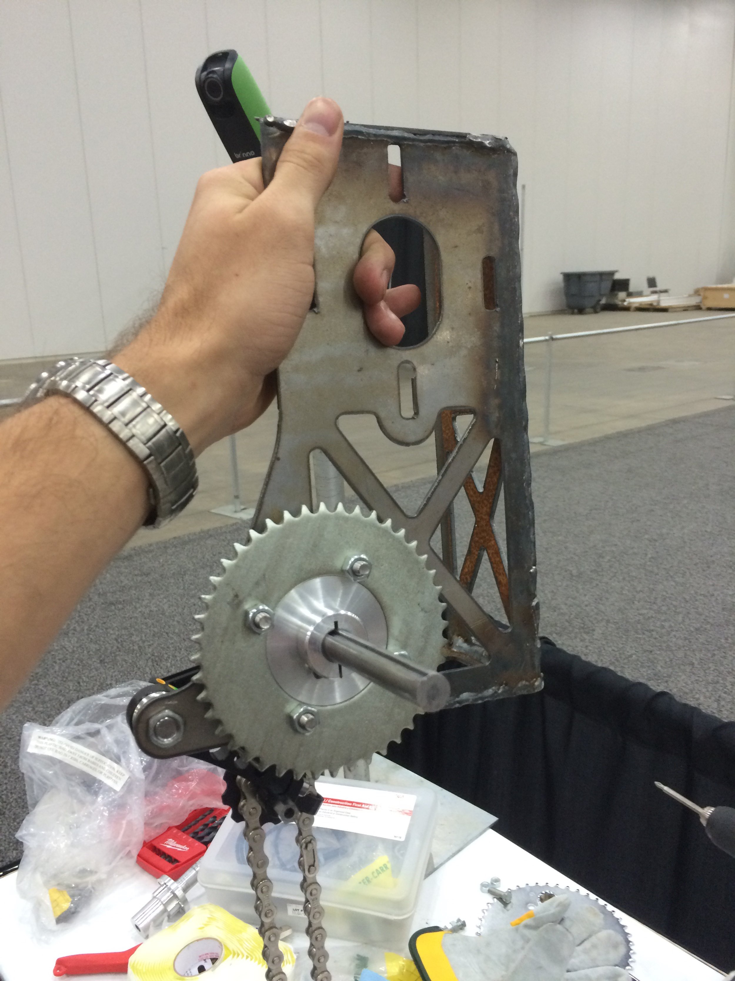
They had attempted to use a double reduction gear setup, opting to mount the intermediate gears and layshaft on some badly-welded thin steel brackets, bolted to the rectangular tube of the wheel mount. Yes, this meant that the entire powertrain sat exposed, outside in the wheel well, as opposed to safely inside the car fuselage.
However, that wasn’t even the main problem. Someone had drastically underestimated the reaction moments these brackets would need to withstand, and decided to make them out of thin 1/32” steel. These were doomed from the beginning to fail under the slightest bit of torque, and indeed we found them completely mangled out of shape.
It was a very poor design.
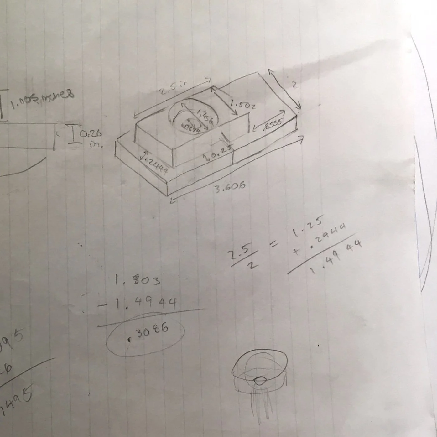
![[IMPORTANT] Gear Ratio Calculation.jpg](https://images.squarespace-cdn.com/content/v1/5f80fba2fa121b5b87b4bd49/8f6e5c8a-e25f-43fd-9771-973c9ed27bfe/%5BIMPORTANT%5D+Gear+Ratio+Calculation.jpg)

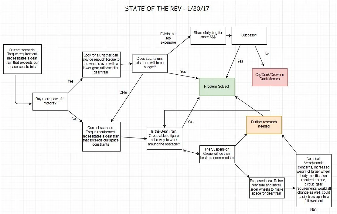
Armed with knowledge of what not to do, we started again from square one with some serious flowchart decision-making.
Taking into consideration the steepest incline in the Shell Eco-Marathon race circuit, and approximating the expected weight of the car, we used basic physics to determine how much torque we would need to put down.
Our target figure was 21.695 N-m of wheel torque. However, our brushed motors were only rated to produce 4.05 N-m.
We considered purchasing new units with higher specs, but decided to save $$$ and engineer our way around the problem instead — Namely determining a gearing option that could multiply our motor torque to the required wheel torque.

An additional thing I insisted on was a dual-motor setup, instead of the single-motor in our existing cars.
A single motor would have meant the driver constantly needing to countersteer to prevent the car from lane shifting.
Dual motors would eliminate that need, and open up so many fun options - Torque vectoring, electronic differential, launch control, and more!

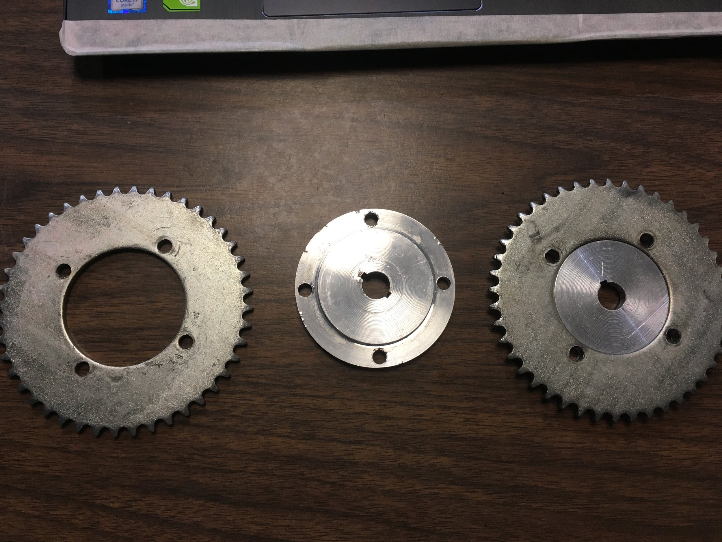
In the continued spirit of reusing parts where possible, Marco and I started disassembling the old drivetrain.
We were able to salvage the intermediate gear and adapter, the 1/2” layshaft they were mounted to, and some bearings that conveniently fit as well.
This was important because it matched the pitch of the motor sprocket, which we couldn’t replace!
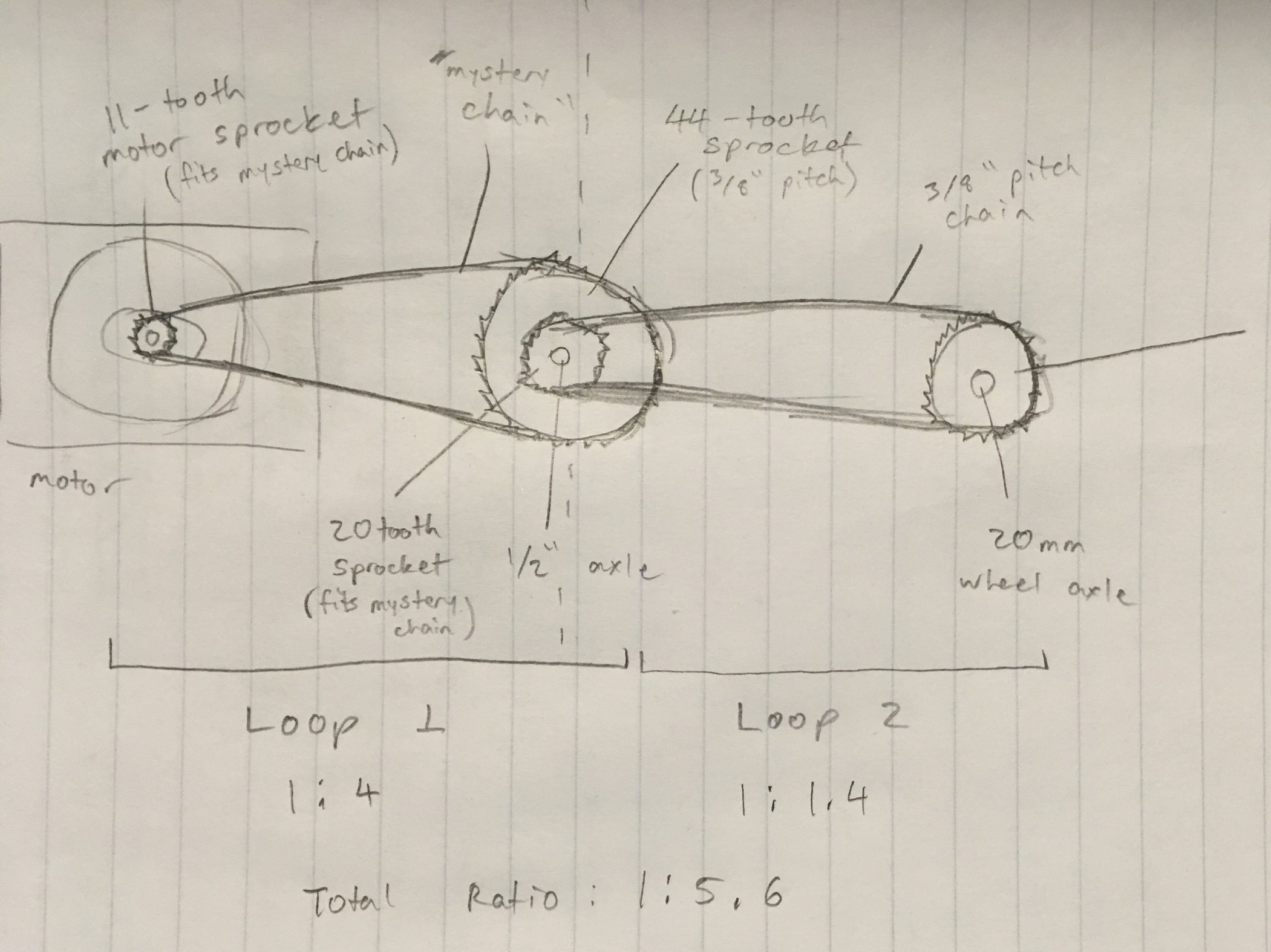
Taking into account our required gear ratio of 21.695/4.05 = 5.36, the parts we were able to salvage, and what was commercially available, I came up with a design with a ratio of 5.6, beating our target value.
I could have gone higher, but increasing torque would mean sacrificing RPM and top speed, which I didn’t want to do.
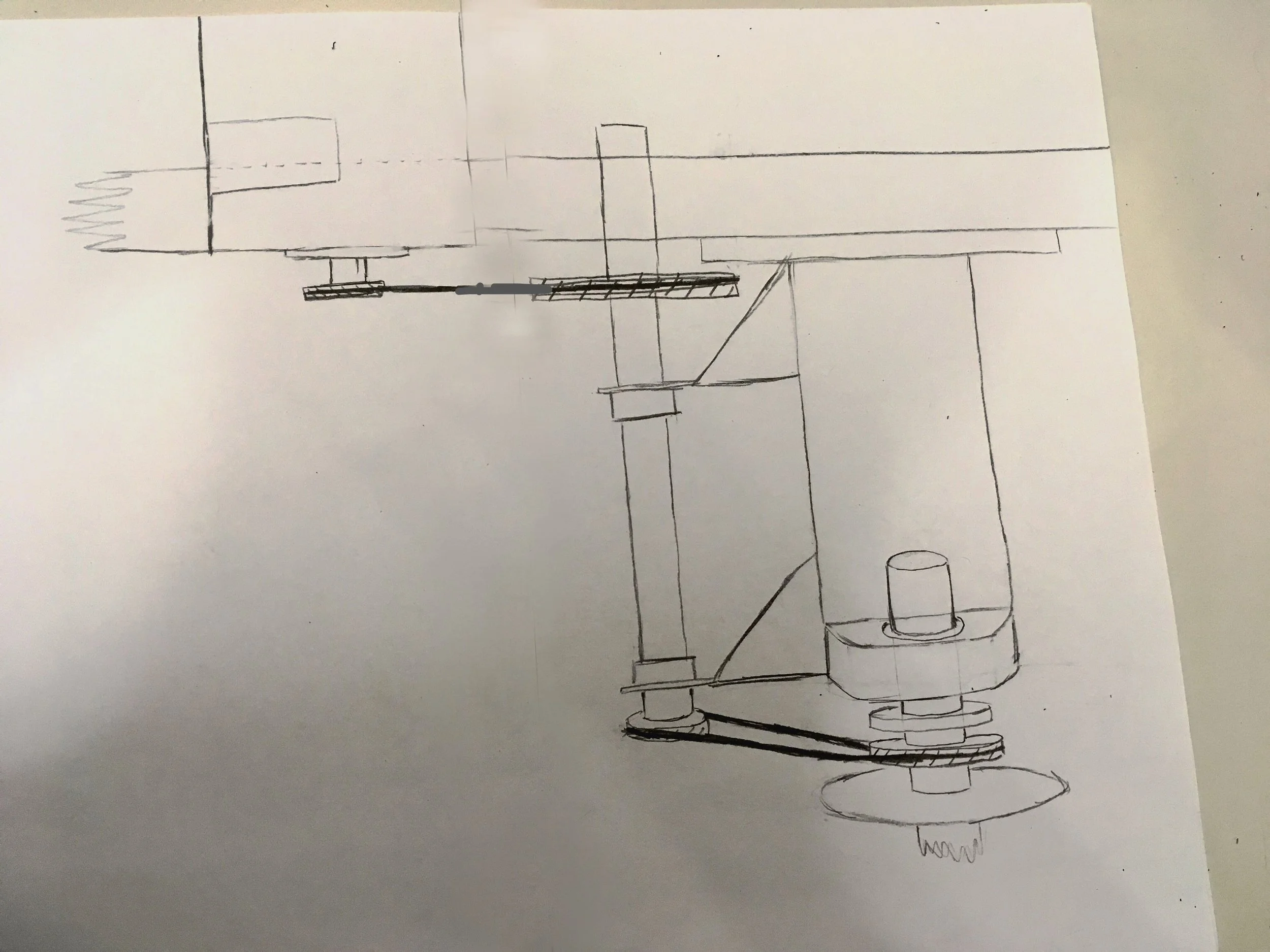
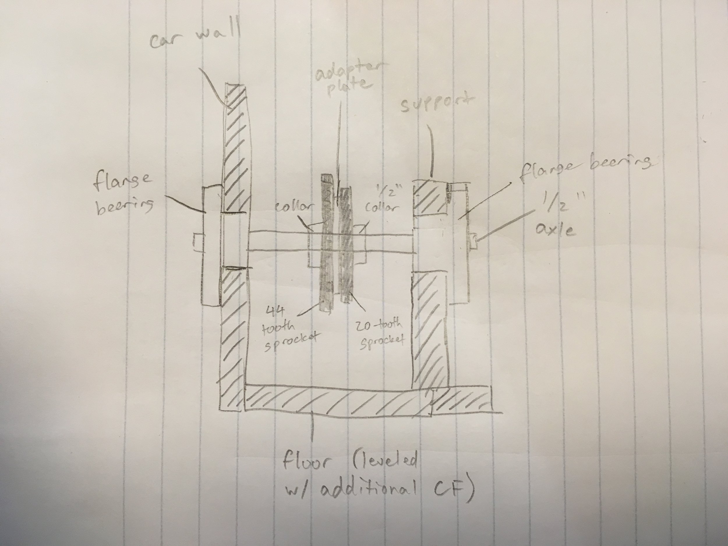
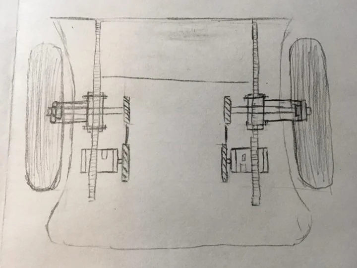
I drew out some schematics: Like the previous teams, we would use a double reduction setup (reduces the rotation speed using two different pairs of gears). However, our powertrain would be housed entirely within the car fuselage, and include a much stronger mounting bracket for the intermediate gear and layshaft.
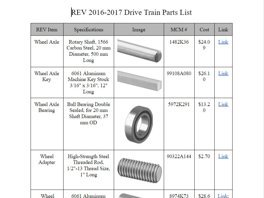
After creating some nice documentation for inventory purposes, we went out and actually ordered the parts we would need.
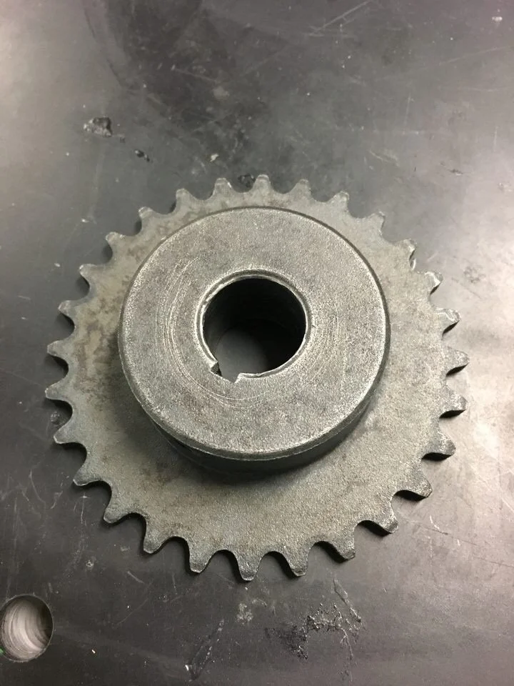


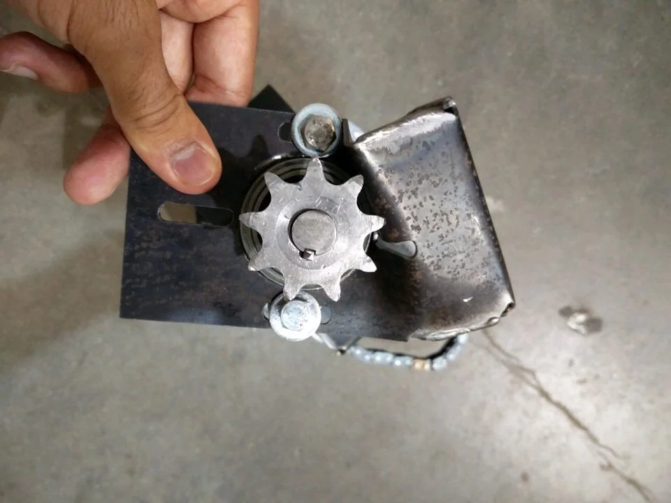
Once our sprockets came in, we lathed our wheel shafts to fit them, then milled out keyways and keys .
Keyways are small channels cut into rotary shafts, that when locked into a complementary cutout in a gear, by small bit of metal called a key, allow them to rotate together and transmit torque properly.

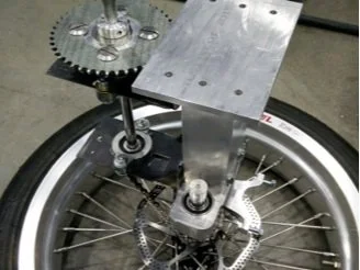
Because we wanted to sandbox our powertrain design, but didn’t want to potentially make mistakes and ruin our carbon fiber body…
We decided to prototype things in wood!
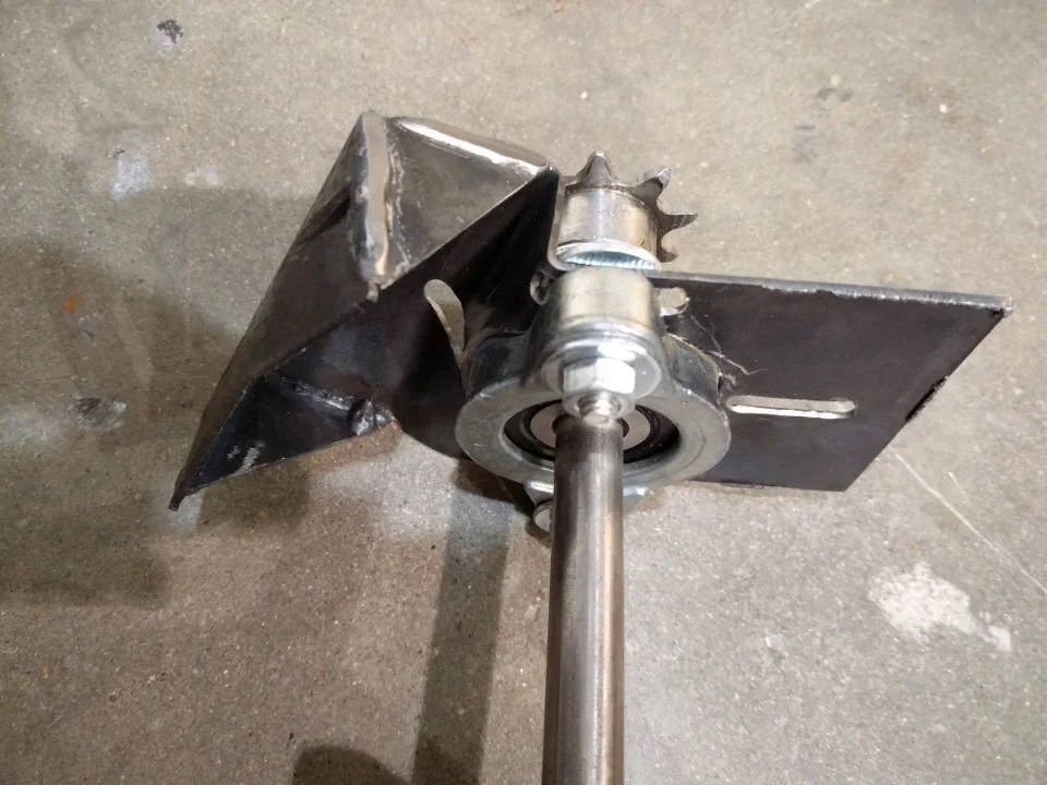
I used one of our salvaged bearings and scrap wood to make an intermediate gear bracket - just for test purposes.
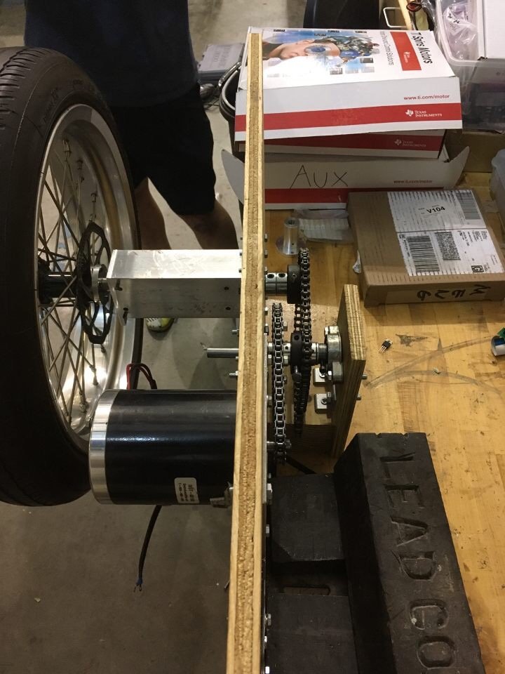
Basically, we built a wooden replica using measurements of our car interior, to visualize and test powertrain designs in.
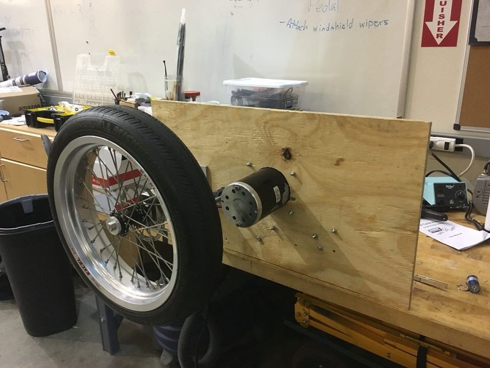
We used a sheet of 1/2” wood to simulate our CF chassis wall, and bolted on our wheel, motor, and gear mounts.

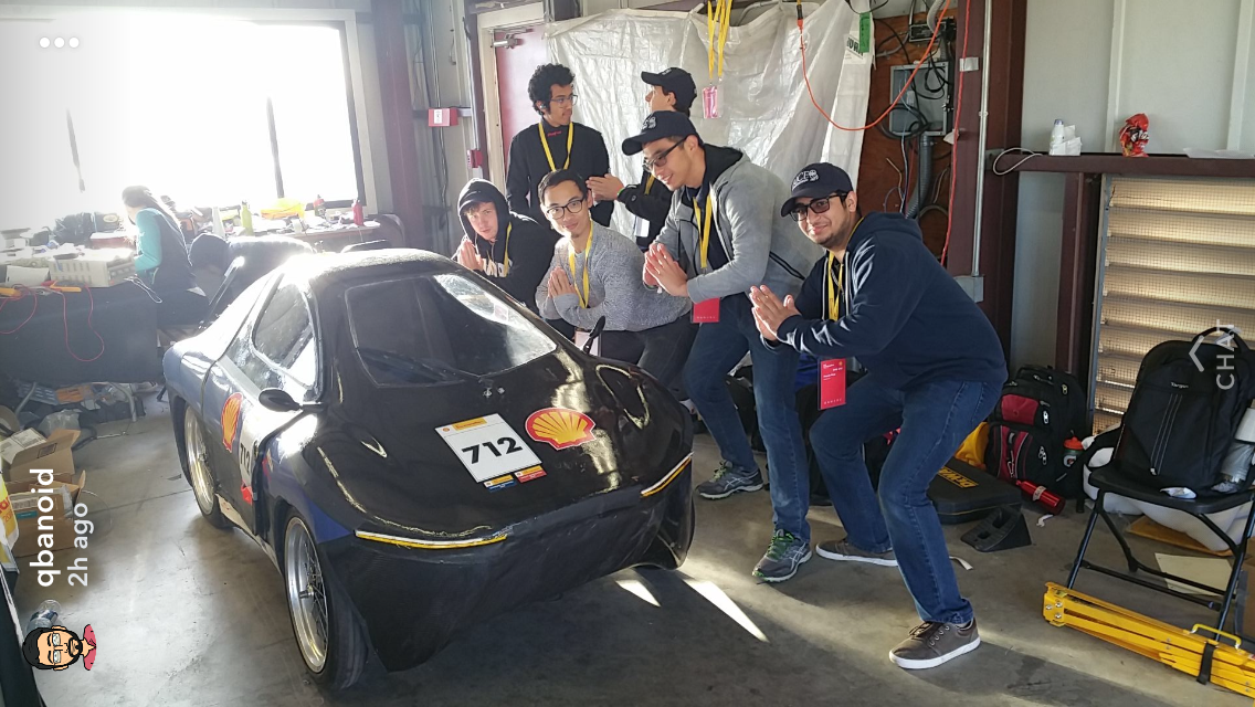
Once everything was ready, we power tested the powertrain for the first time!
I removed the wheel to reduce the risks associated with a heavy object revolving at high speed.
As you can tell from our celebrating, it worked quite well!


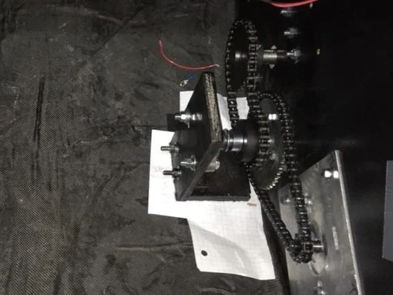
At some point, I spray painted the wood black to look better in photos. Also matched the black carbon fiber better.
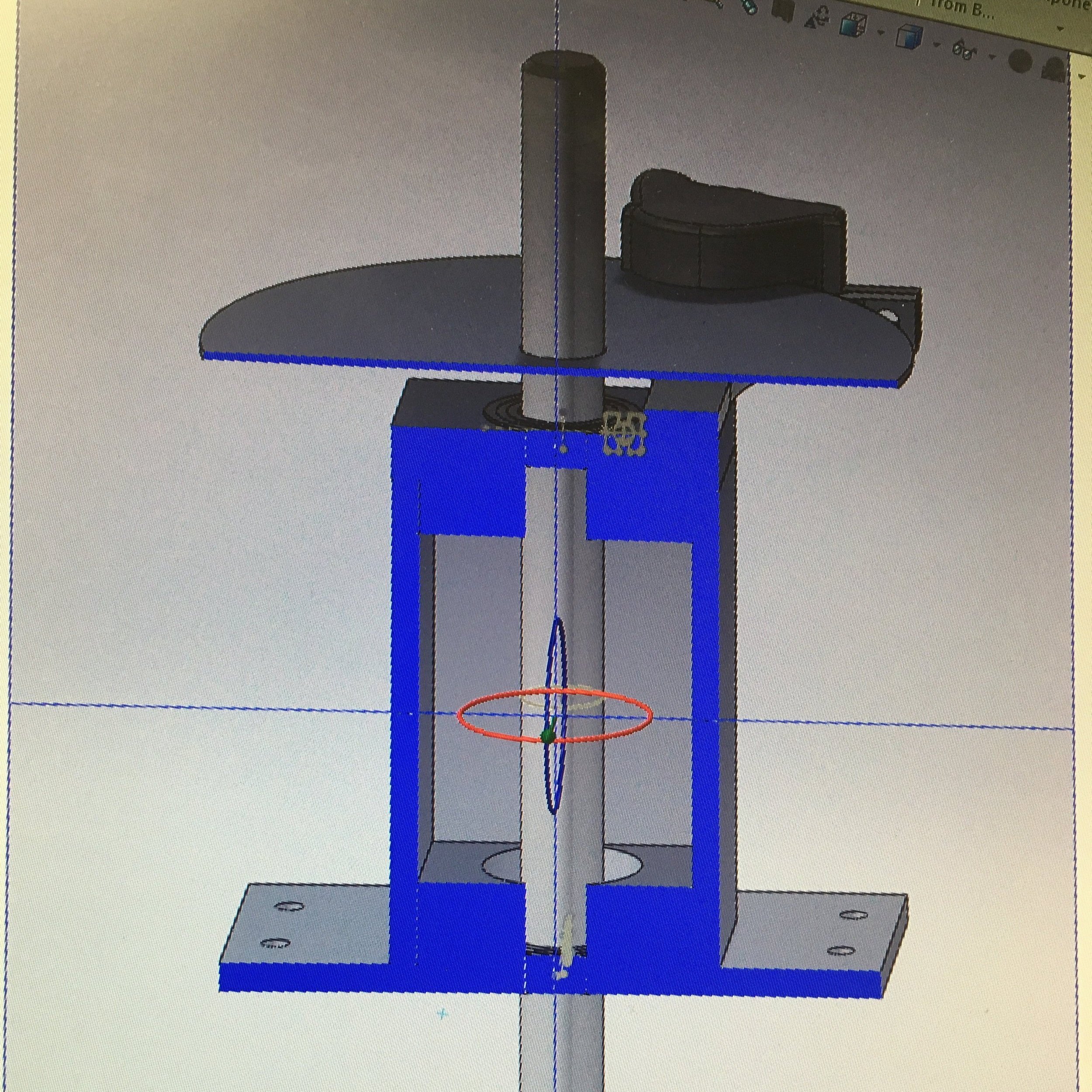
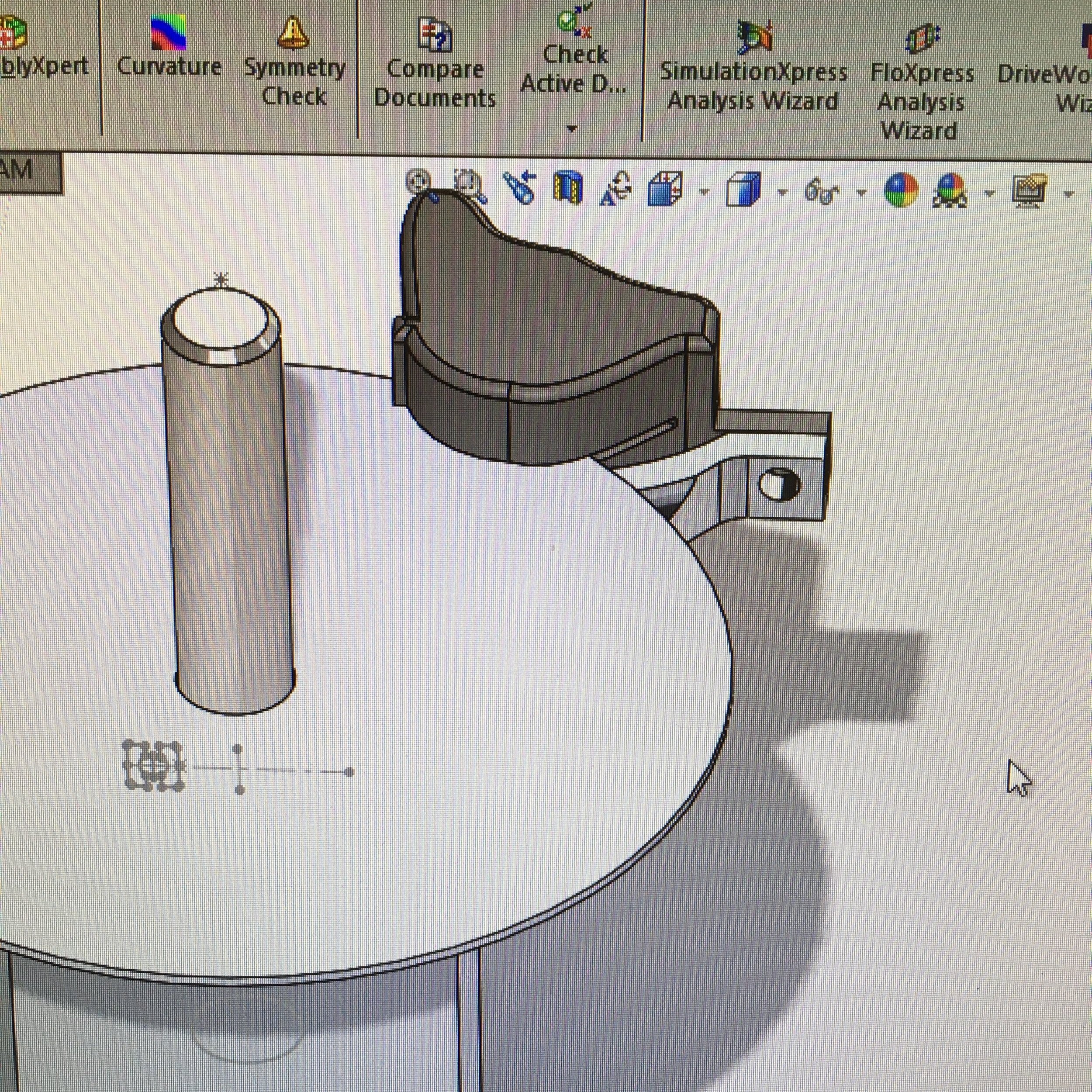
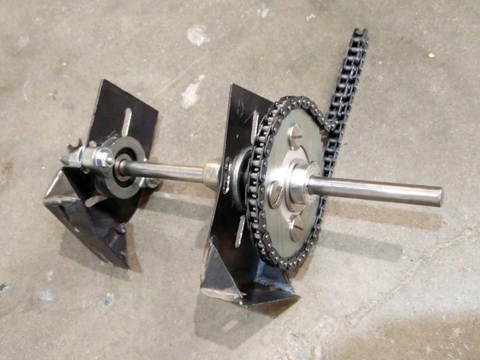
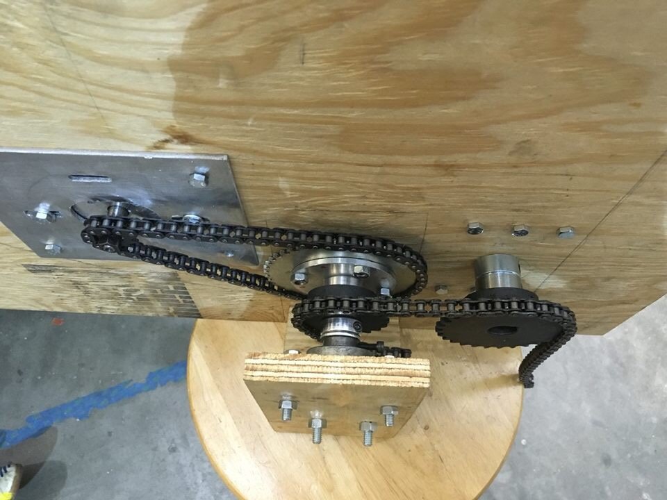
Here is a labelled diagram of my drivetrain system, with the intermediate bracket removed for clarity.
And another, clearer shot of the drivetrain in action! So clean 🥰

The next step was to transplant our functioning powertrain into the car, like a surgery!
Due to the trunk bottom being curved, it was very difficult to ‘place’ the intermediate brackets and position the drivetrain correctly in general. I came up with a genius (!!), multi-step plan to do it:
(1) First, I stuck a large patch of Velcro on the trunk floor, and the opposite Velcro underneath the wooden bracket.
(2) Before I placed the bracket on the trunk floor, I stuck in a sheet of paper to prevent the Velcro from grabbing as I shifted the bracket around, looking for an optimal position (chains tight and parallel, no clearance issues, etc.).
(3) When everything had been positioned correctly, I pulled out the paper, leaving the velcro to stick everything! This kept the parts from sliding all over the trunk as I did the last step…
(4) Which was to finally drill through both bracket and CF body together, and bolt everything properly.
It worked super well and I was happy the idea came to me quickly, as opposed to us being stuck for days or weeks on this.

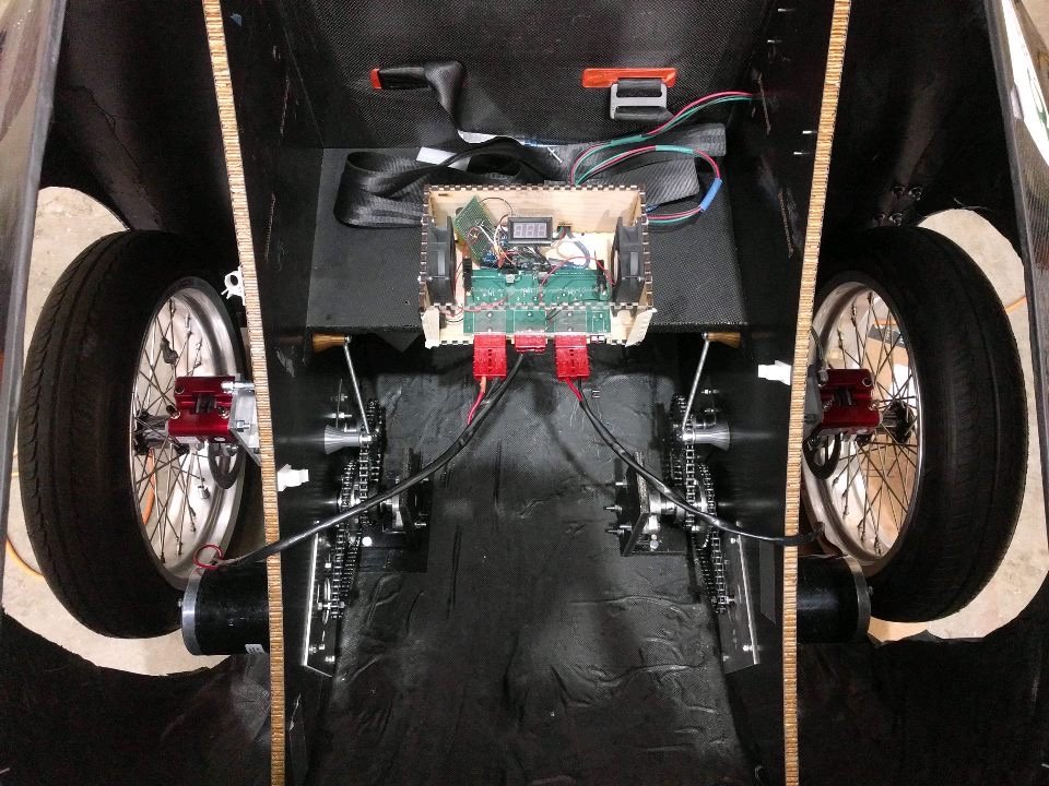
From there, it was simple to repeat the previous steps and create a mirror-image drivetrain for our second motor!
Things are coming together!

With the ELECs’ help, we tested the drivetrain as installed in the vehicle for the first time.
The first video is us testing a single motor (the rubber-looking thing was surgical tubing we used to tension the chain), and the second video was a full test, with both motors powered and running! It sounded magical 🥰🥰
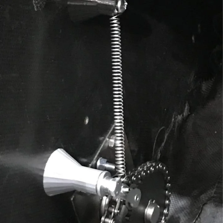

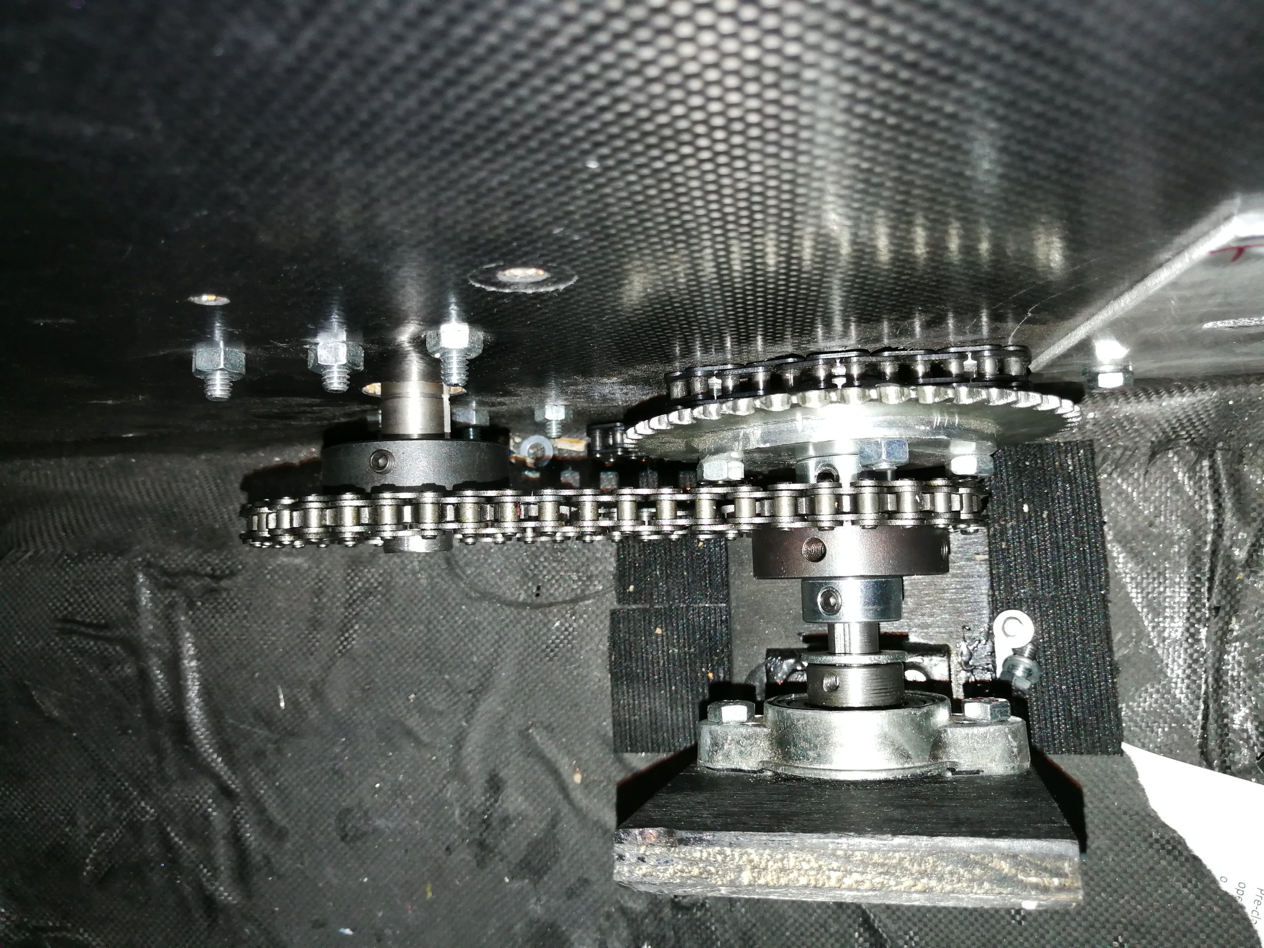
Eventually, we upgraded all of the drivetrain components to higher-fidelity materials.
We replaced our surgical tubing tensioner with a proper 3D-printed mounts and a heavy duty extension spring,
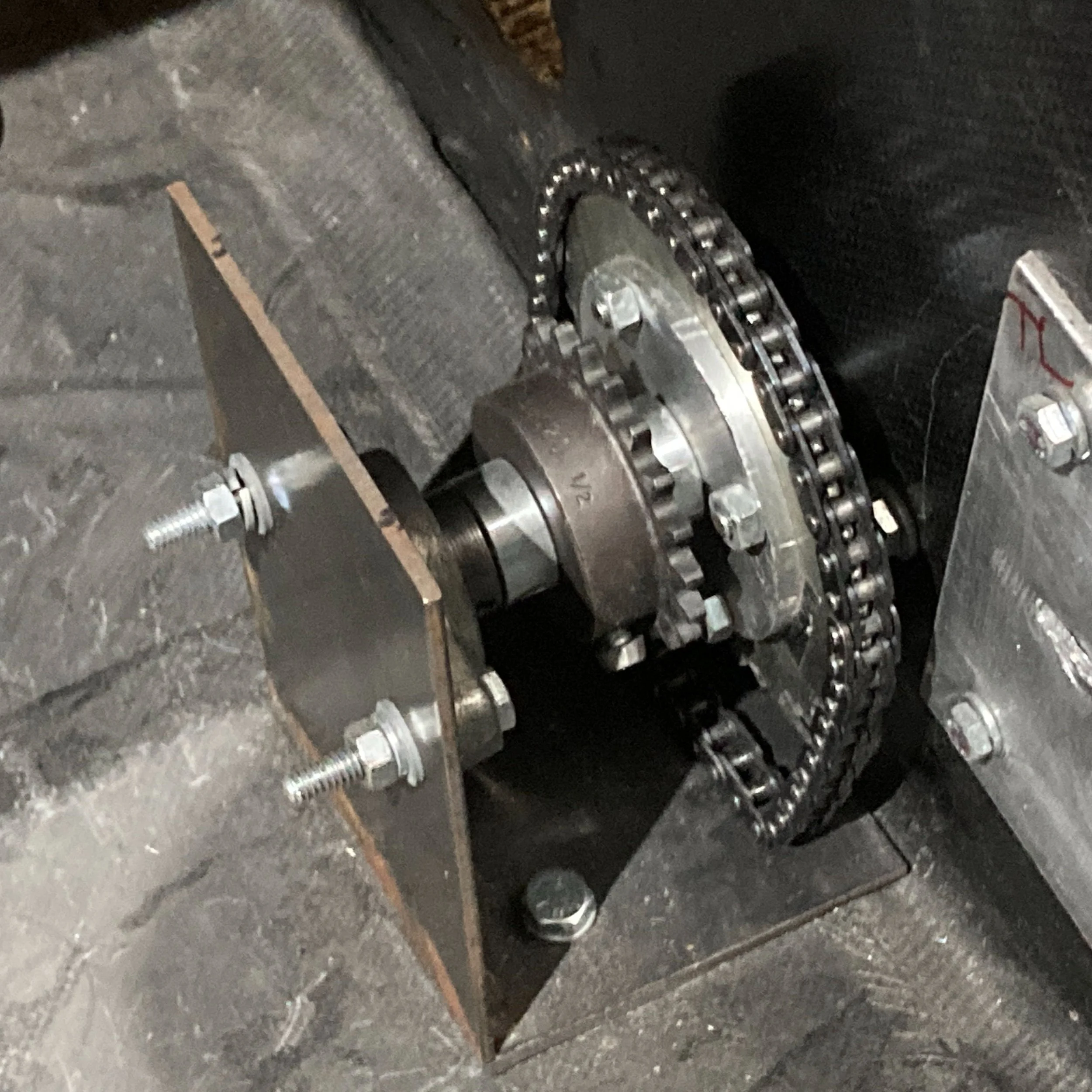
And the wooden brackets with properly cut and welded steel ones! We also removed the Velcro 👌
All in all, what an absolute transformation!!
Both in improvement from the previous team’s solutions, and from my own concept drawing to alive and kicking in real life!
This drivetrain is by far the subsystem I’m proudest of having worked on.
brakes


Shortly after completing the drivetrain, I received an email that signalled a lot more work for the team.
Shell Eco-Marathon had updated their rules, this time banning all bicycle brake components.

Which was horrible for us, because we had initially planned on using bike parts, and designed many of our parts around bicycle disc brakes we had purchased!
Time to remake half of our parts, I guess ¯\_(ツ)_/¯


After researching and speaking with some go-kart shops, we decided to run 3mm go-kart discs!
Heavier-duty discs means our original bike calipers would need to be replaced with heavier-duty ones as well!
While we did the math and realized this setup would provide far more braking force than a vehicle of our weight would ever need, it was the only way we’d be allowed to race in the Shell Eco-Marathon.


To mount these new discs, we designed additional parts that could work with our existing wheel shaft coupler.
The brake discs are sandwiched between two of these puck-looking mounts, to be able to mount to a 20mm shaft.
We cut keyways in both the brake disc mounts and wheel shafts.


Here are the brake discs and ‘pucks’ attached to the wheel driveshafts! Remember these?
The second picture looks kind of like a dumbbell 😅
With that, the brake disc situation was settled.


For the brake discs to do any actual braking, they need to be gripped by brake calipers! That’s what we figured out next.
We mounted a pair of hydraulic master cylinders to the car’s firewall, and fabricated a brake pedal with scrap aluminum.
We connected the cylinder and caliper using hydraulic brake line, flushed them with Dot 4 brake fluid, and bled out all of the air bubbles. Final gif is the brakes clamping open and shut!
Updated Rear Wheel Mounts

While we now had the brakes working, the increased thickness of our new brake calipers meant they wouldn’t fit our existing wheel mounts anymore!
We were forced to modify the design and create a new, shorter rear wheel mount.


By this point we were machining pros, so we machined out both new rear blocks in a day!
In addition to shortening and widening the wheel mount block, this design included a few more improvements.
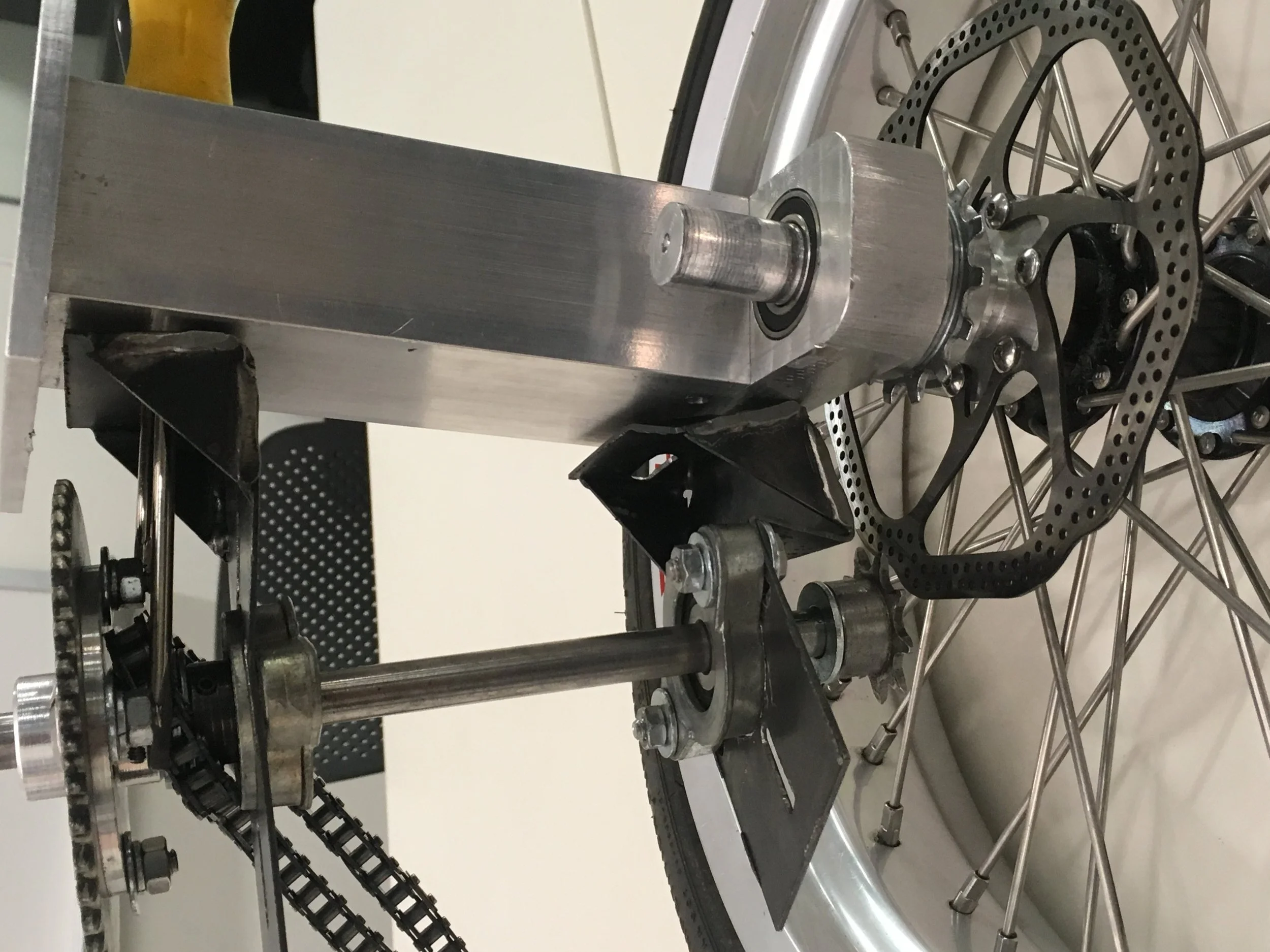
While we had used tension pins to fasten the previous mounts together, this time we used shoulder screws for easier disassembly! We also included tapered Timken bearings to resist axial forces into and out of the mount, something the radial bearings in previous designs weren’t able to do.
Mocked up with a wheel shaft and wheel.


This shorter suspension block allowed us to bolt in our new brake calipers and have things actually fit!
After fully assembling and re-installing in the car, I manually spun the wheel to confirm brake disc/caliper clearance. There was some wobble, probably from shipping damage to the discs, but everything still worked well!
Re-confirming drivetrain compatibility and operation with new ‘suspension’.
Just listen to those motors SCREAM!
Success!
Front Wheel Mounts & Steering


So far, this writeup has exclusively covered the rear end of the car. What’s been happening in the front?
Why, steering, of course!
The parts pictured were some steering knuckles we dug out of storage, and wanted to incorporate into our new car.
To do this, we again used our now-traditional aluminum block-and-plate mounts, and attached out steering knuckles to them.


With the steering knuckles installed, we still needed a way to push/pull on them to swivel them left/right, in addition to also needing to mount our front brake calipers.
We thought of a ‘wing-and-fin’ design that could address both needs, as visible from our beautiful Cardboard Aided Design:
A horizontal ‘wing’ to bolt to the steering knuckle & pick up the steering tie rod, and
A vertical ‘fin’ to mount the brake calipers
Once we had an idea of what we wanted to build, we hopped into Solidworks once again and made models for everything.


We laser cut wooden versions with properly-positioned bolt holes, before committing to making them in steel.
They fit perfectly on the first try, with brake disc / caliper clearance issues whatsoever. All thanks to Solidworks!
Once all of our dimensions were finalized, I hopped on a mill and began cutting the wing and fin out of 1/4” steel plate.
Here they were before and after being slotted together!

Next, we drilled all necessary holes, added angle brackets for reinforcement, and mounted both assemblies into the front wheel wells.
The gold looking piece is a ball joint connected to the tie rod I mentioned!
When that joint is pushed or pulled left and right, it rotates the entire wing/fin about the steering knuckle axis to turn the wheels.

The other end of the tie rods were connected to a rack-and-pinion steering assembly we also had around. I added a wood block to solve some clearance issues, and the stamped aluminum piece underneath was also an inherited piece.
Late night pic of myself and Mayank installing the steering rack!
Shell Eco-Marathon

OK, let’s review.
At this point, we have a body on 4 wheels, functioning powertrain, brakes that brake, and steering that steers.
I dunno about you, but that’s a running car by my book!
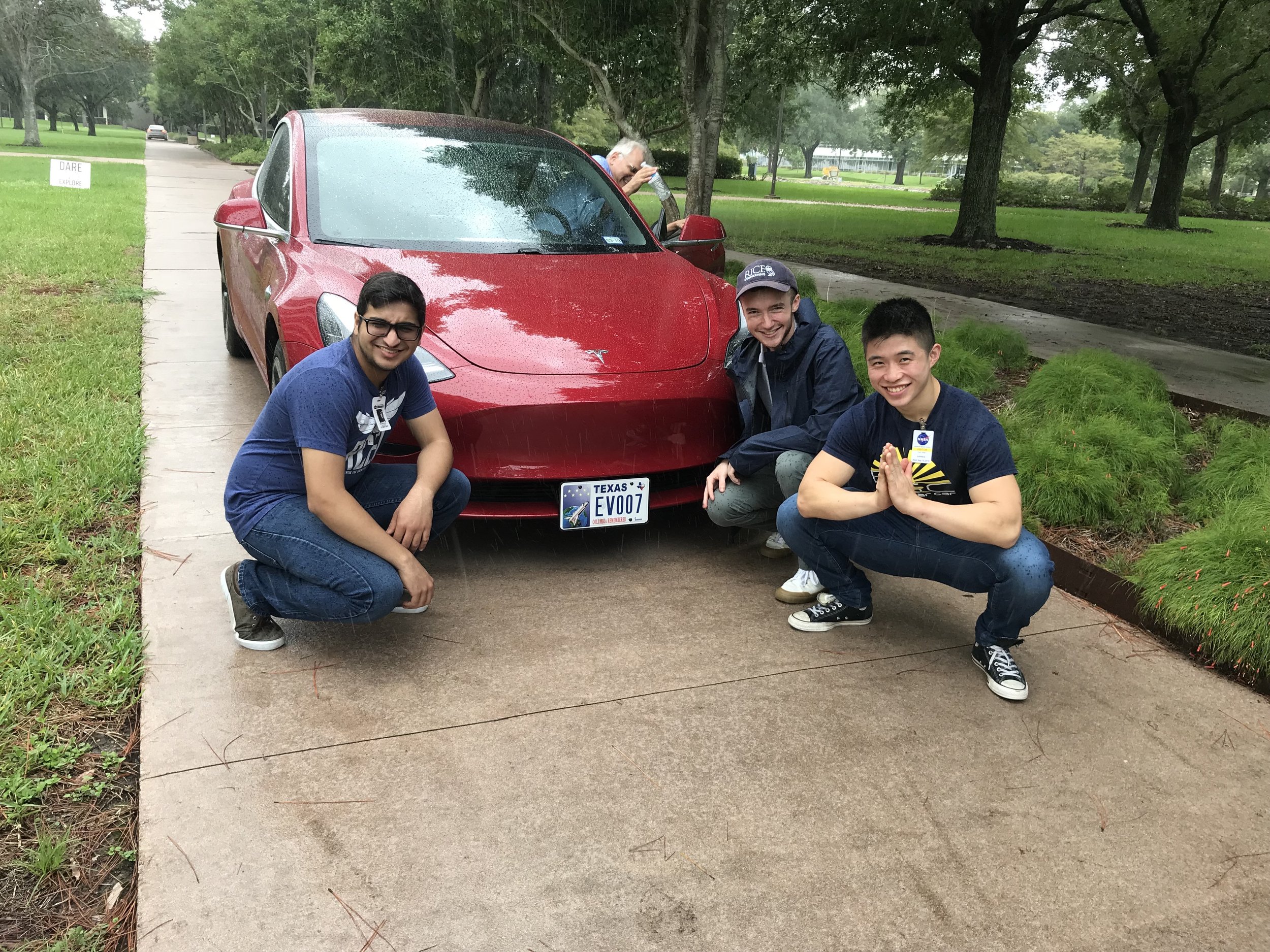
Some successful rainy day road testing!
It was a long road to this point, but we had done it! We had built a fully battery electric, carbon fiber-bodied, 4-MFing-wheels-having, CAR!!
And just in time, too! Shell Eco-Marathon was just around the corner.

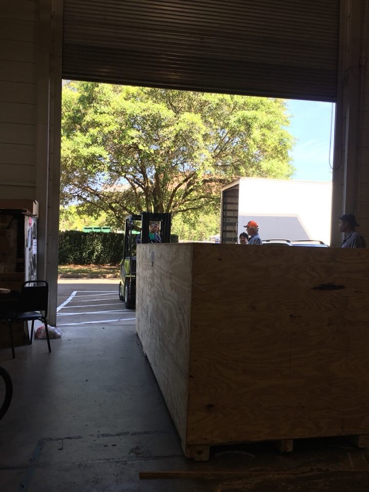
So we loaded it into a crate, strapped it in snug, and had it forklifted into a truck bound for Sonoma, California — where our competition would be!
Shipping costs were actually a significant part of our budget. It’s not cheap to truck something ridiculous like this cross-country and back.

Final race prep took us until 4 AM, after which we went to House of Pies for some junk food. Hell yeah
One week later, the team flew out to California 🏖️


(1) Tent city! To avoid paying for a hotel, we brought along and camped in the REV team tent!
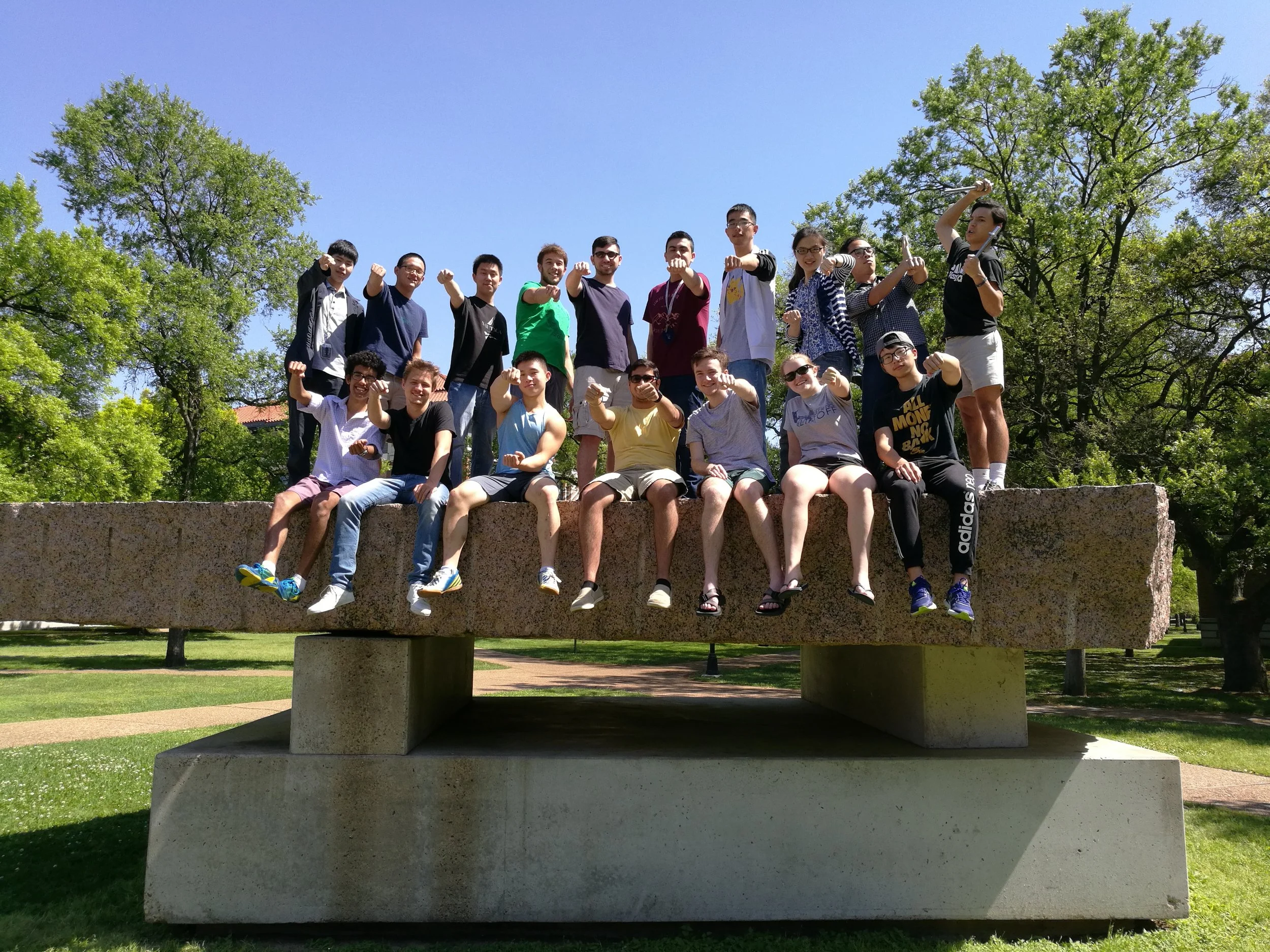
(2) The squad power walking around bright and early the next morning!
(3) Good to see our girl REVolution made the shipping journey in one piece!

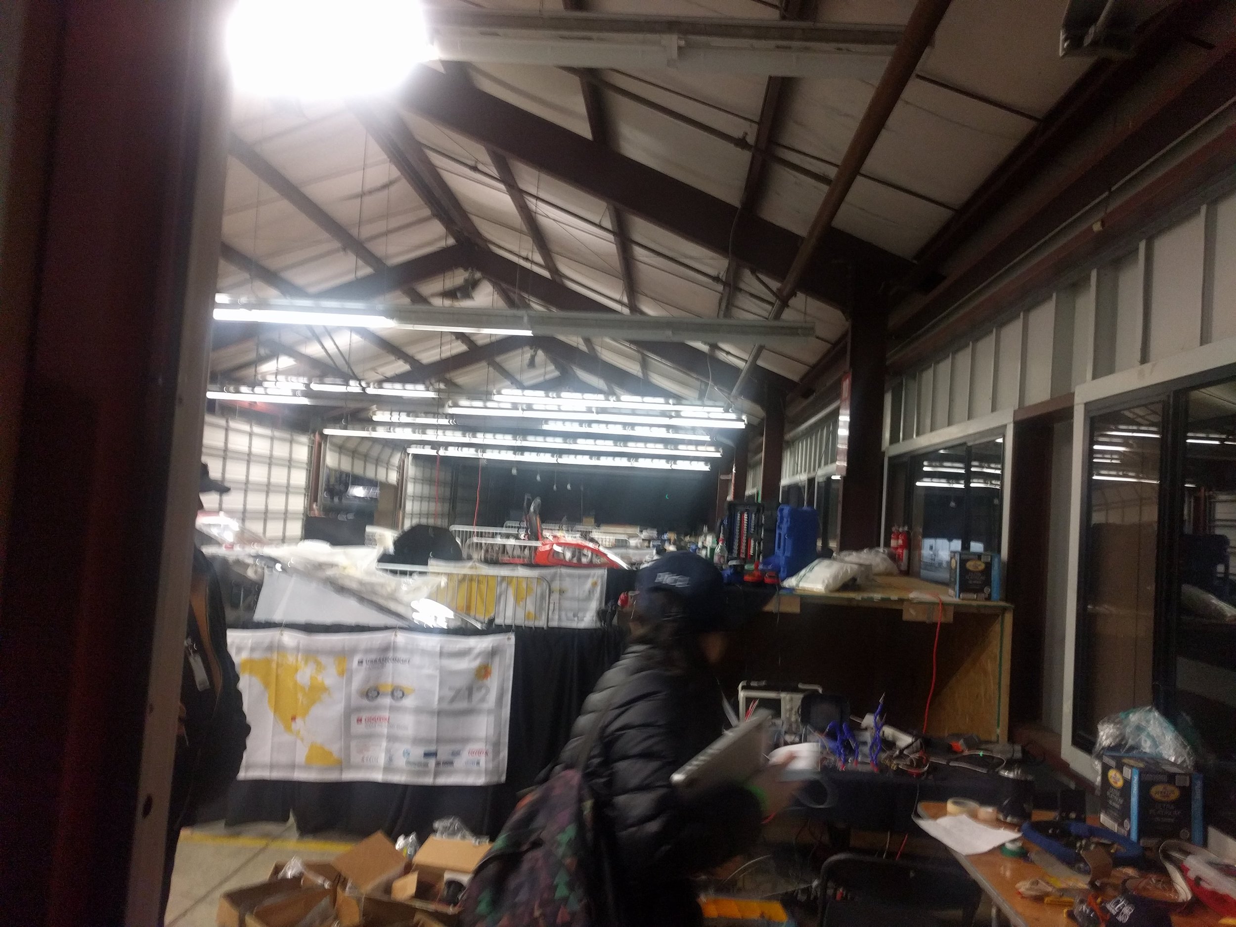

The next few days were a delirious mess of final tuning, troubleshooting, and looking for misplaced tools. Before we would be allowed to race, we had to pass safety and technical inspections, so of course at the last minute we realized there was still a huge laundry list of tasks to do.

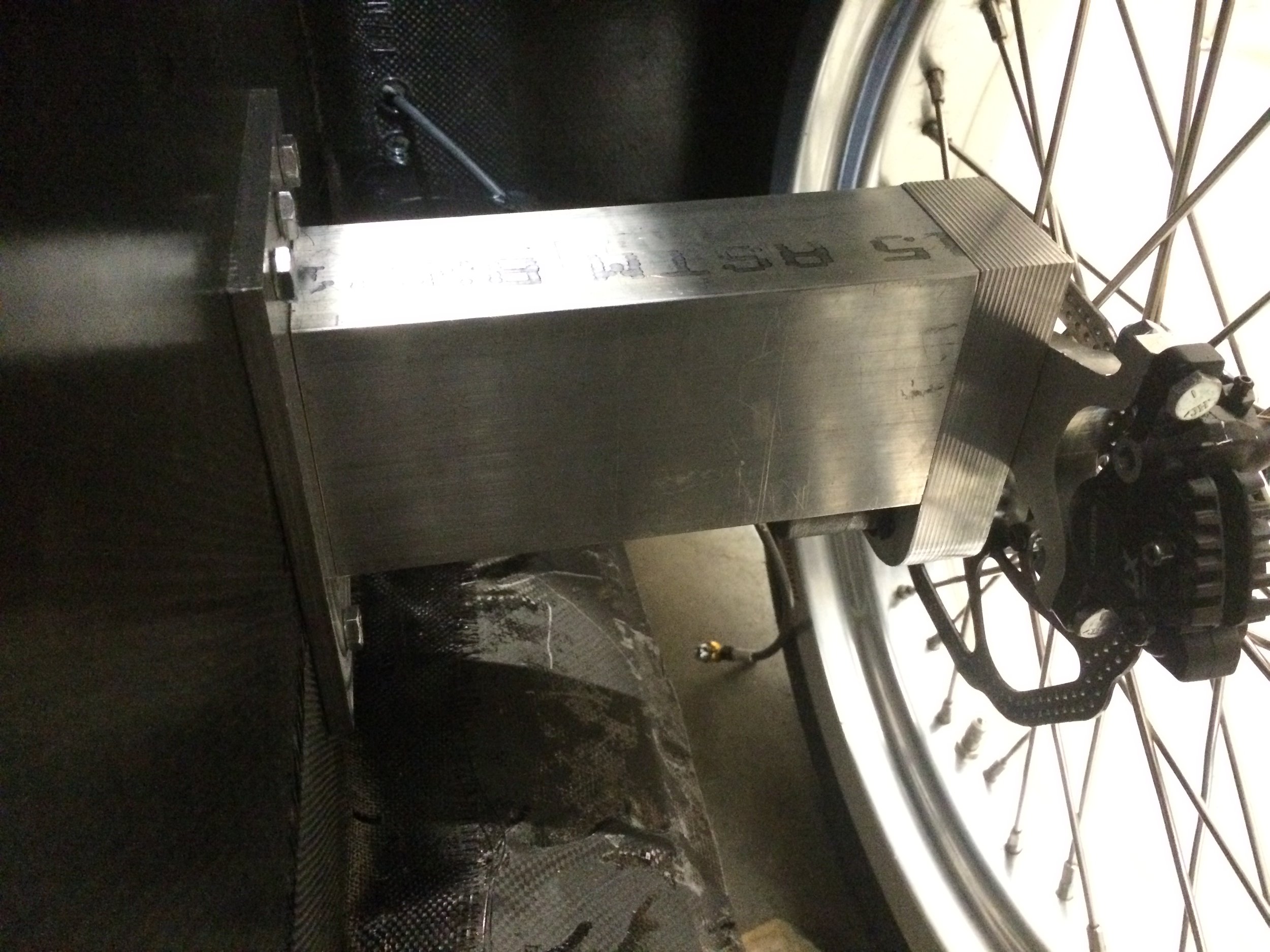
SEM officials installed this block in our car. It was a telemetry system for tracking times, GPS, and power consumption.
It was spliced in directly between the battery and the rest of the car’s circuit to ensure we weren’t reporting false efficiency figures - as that, opposed to speed, was what was scored in the Eco-Marathon.
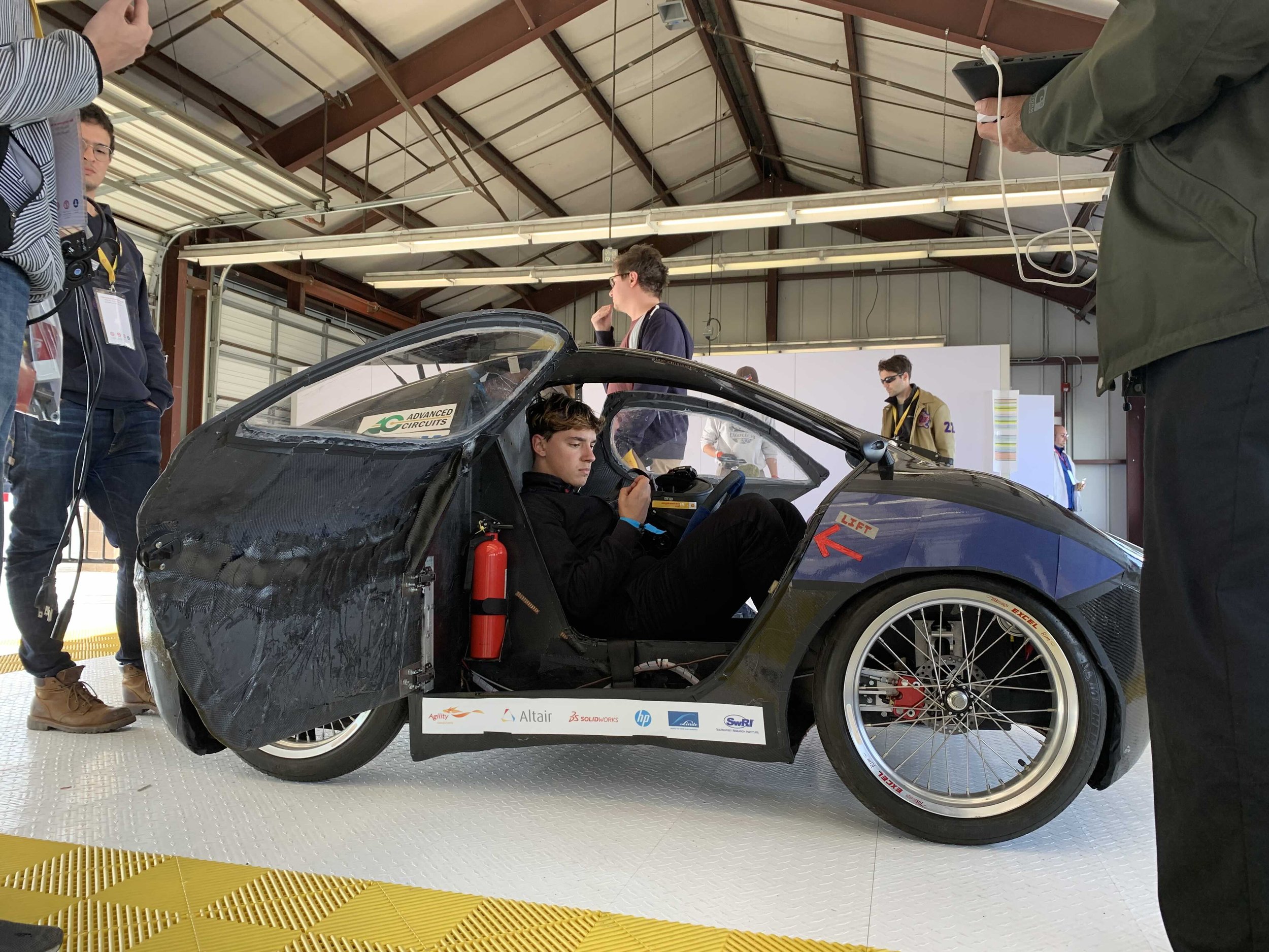
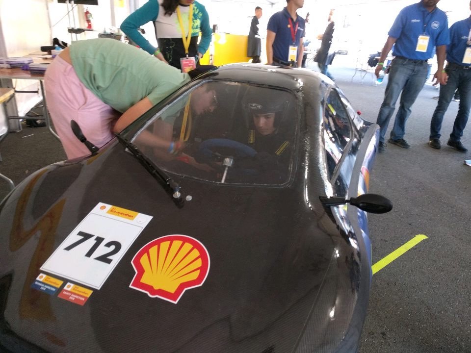
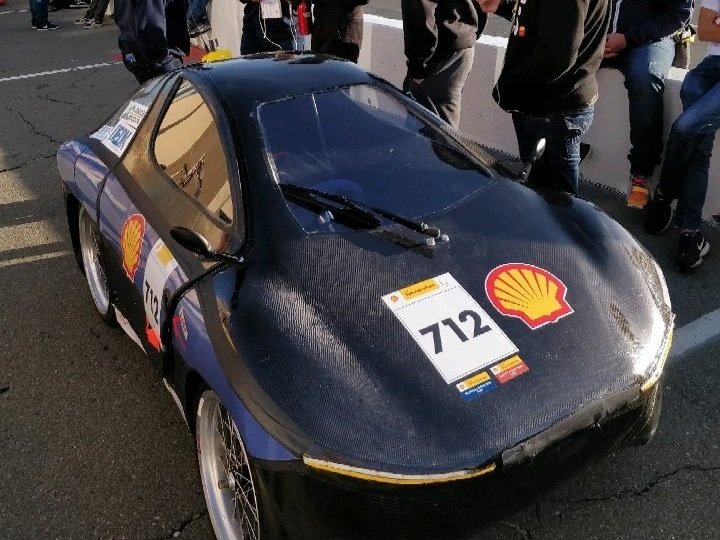
The inspectors came around, and we passed safety and tech inspections with flying colors, earning the small blue and red stickers below our 712 race livery!
Some tests performed included not losing traction while braked on an incline, vehicle roof being able to withstand a certain amount of weight placed on top without bowing or collapsing, and the presence of an E-stop (electronic kill switch).
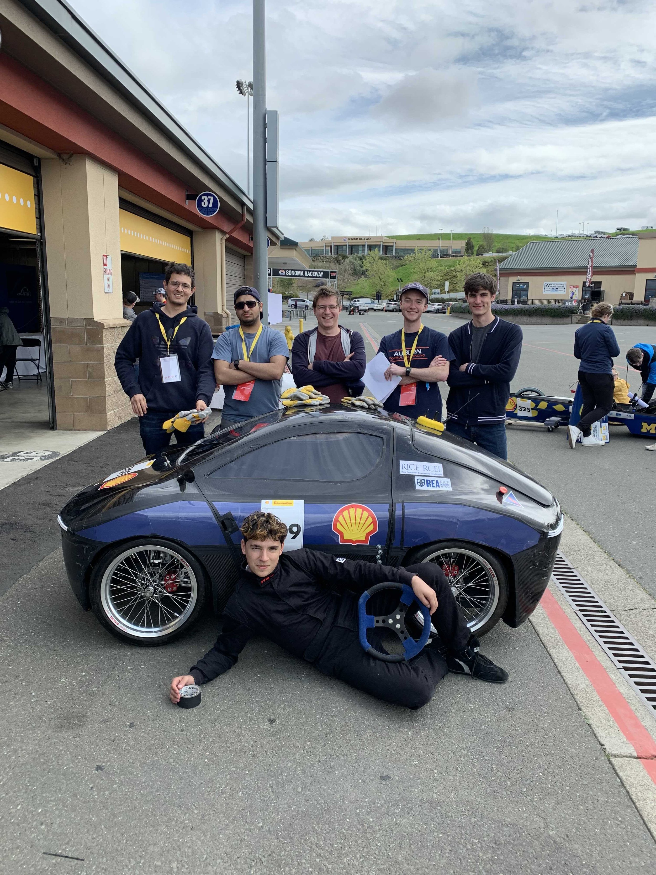
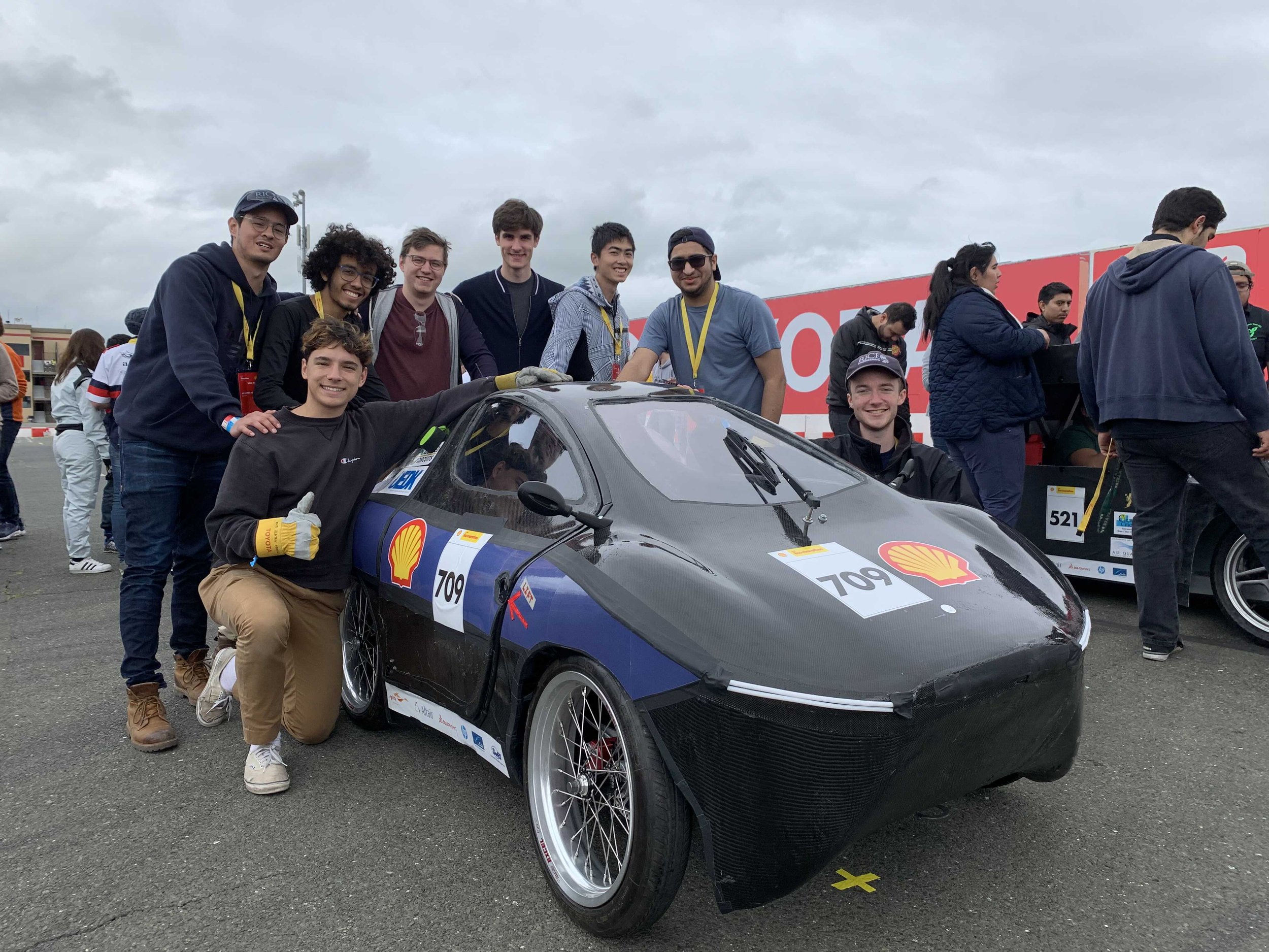
After inspections, we had a brief window for photo ops before heading to the race paddock 📸

At the starting block!
Regrettably, past this point I would be too caught up in the excitement to take many more more good photos.
REVolution ran beautifully for a lap and a half, but after that our homebrew motor controller blew out and she was forced to retire.

But yes! This for the most part brings a close to the REVolution’s story.
It performed admirably and we learned so much from it.
New beginnings

After we retired REVolution, it was time to for a fresh start.
It was time for a new design cycle, and a new vehicle to go with it, code named REVize (I pushed for REVangelion but no one got the joke 😔)
This was both to escape some problems inherent in our inherited design, as well as to give incoming freshmen opportunities to gain experience and give input, rather than be stuck with a design they hadn’t had a say in.
We weren’t going to repeat the mistakes of the team’s past.
A major problem with the former CF chassis was its lack of any *real* rigidity. Sure it held up, but any movement would cause creaks throughout the body, and cringing throughout onlookers.
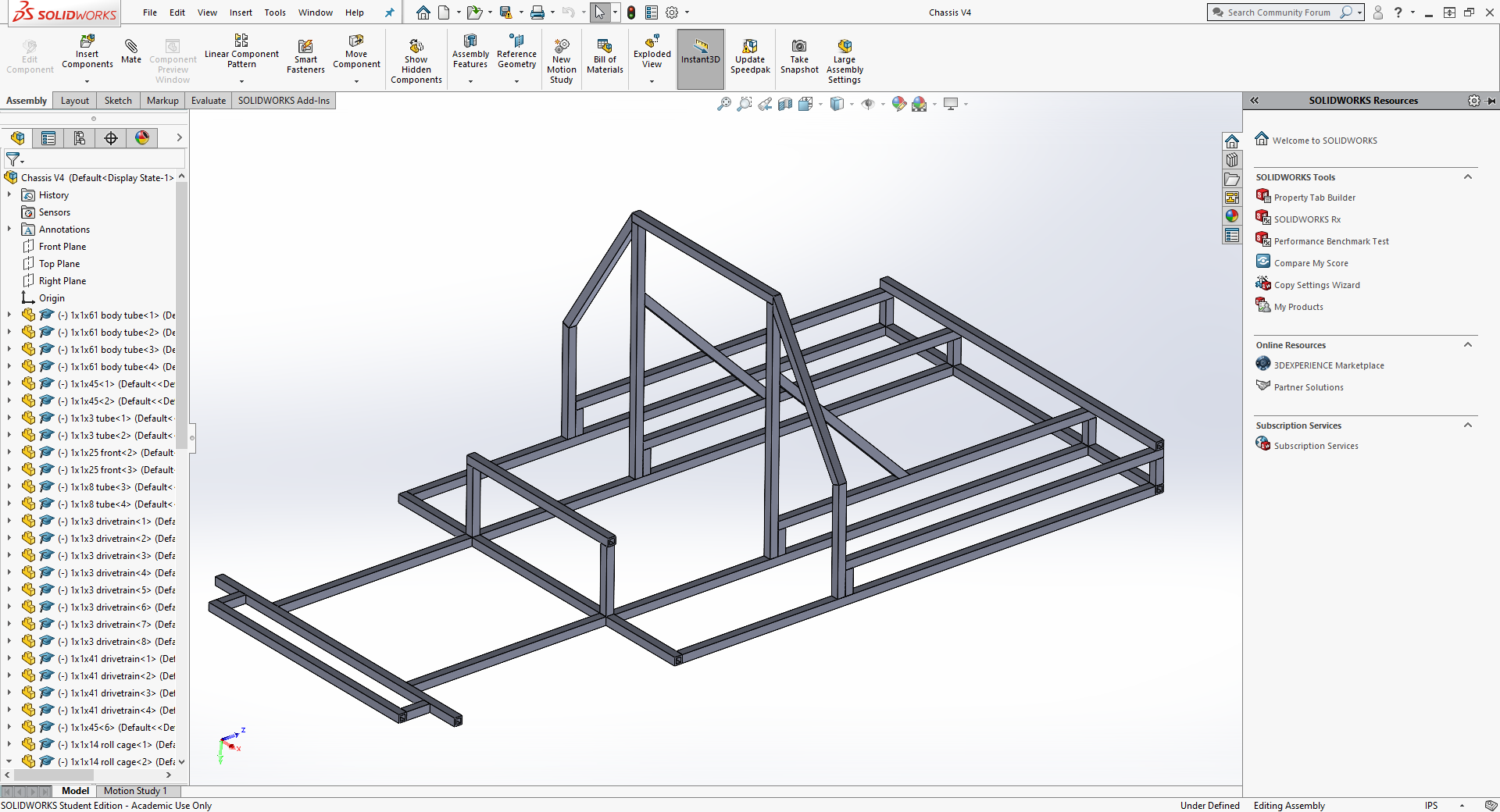
To mitigate this, we designed a steel tube chassis in Solidworks to use instead.


We ordered multiple yards of steel tube, thoroughly mystifying our college mailpeople, and set about cutting everything to length with a Johnson saw.
Once we had all the chassis members cut and labelled, I personally started welding the main structure, to make sure everything started level and square. After that, members took turns to each get some experience.


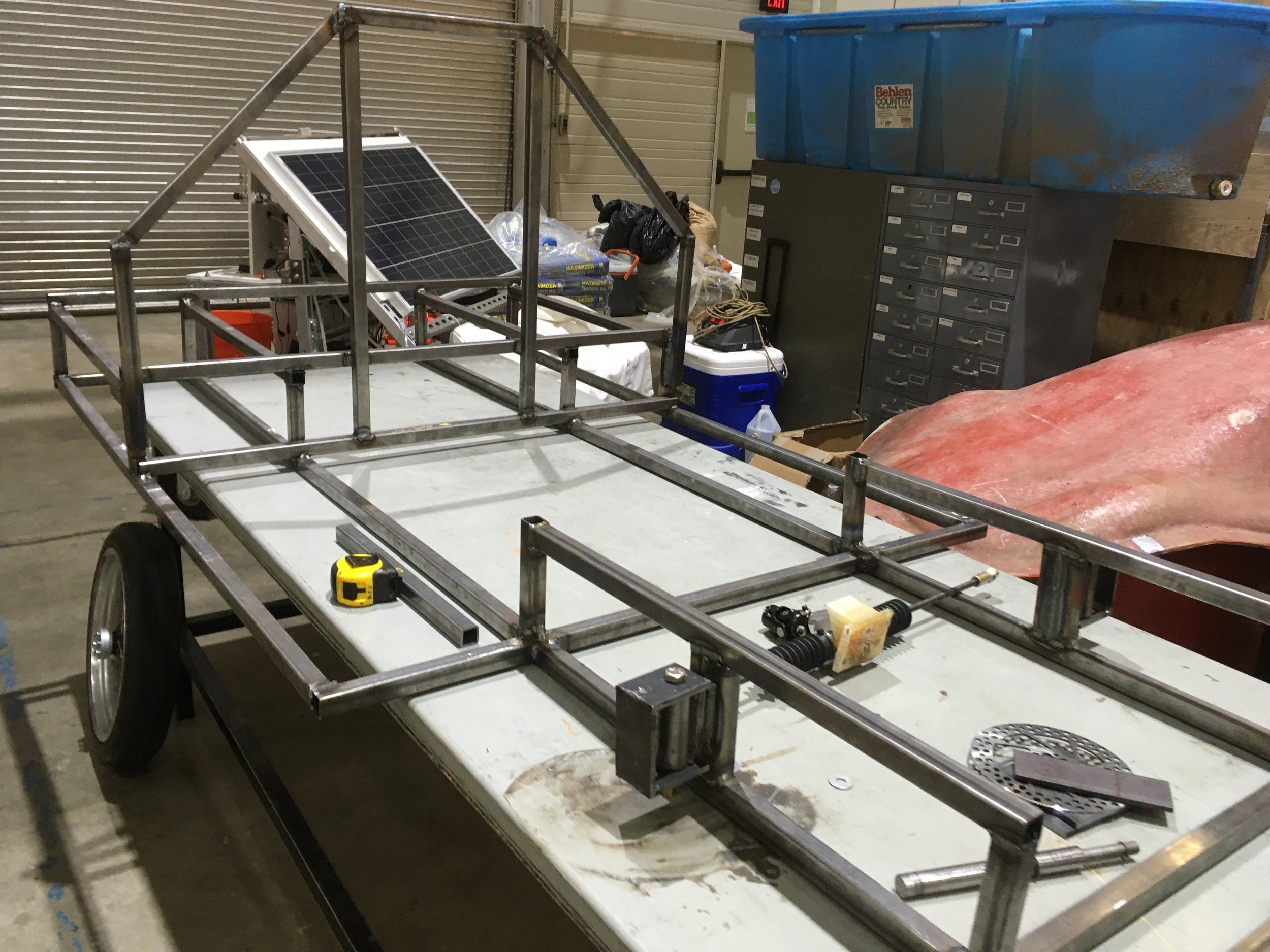
More welding happened, and gradually the stack of metal tube began to transform into an actual frame!
Here I am posing in a work-in-progress chassis!


With a brand-new frame came the possibility to redesign and simplify some systems!
As we were abandoning the overly-complicated knuckles and wing/fin design of REVolution, I designed an ultra-simple steering system.
The axle is welded to a C-shaped steering knuckle, which rotates about the chassis via mounted bushings and a retaining bolt.
We machined some bushing mounts out of steel stock, and welded on some square tube sections to create a flat chassis mounting surface.
Not the prettiest, but they’ll do.


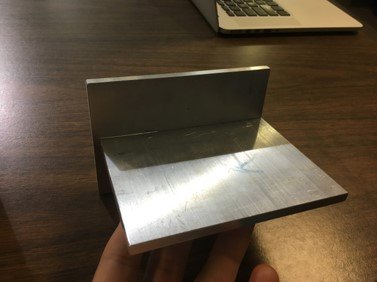
I band sawed steel plate to size and welded them in a 90° jig to create the aforementioned C-shaped steering knuckles.


(1) We welded this entire assembly to the chassis, and you can see how the steering knuckle is meant to turn.
(2) As before, the same rack and pinion unit would push/pull the knuckles left and right to turn the front wheels…
(3) And is attached to the knuckle using a series of tie rods and ball joints. The rack and pinion unit bolts into a 3D-printed mount, which itself bolts into an aluminum floor pan.
Here is a chassis / steering overview video Allen and I recorded! It basically covers the end product of the previous ~15 pics
Please excuse my cameraman’s loud breathing, and my own long unkempt hair.

Finally, the racing seat, brake caliper mounts, and rear motor mounts were welded in.
The next steps would be to finalize the drivetrain, and create mounting points for a new, removable-fiberglass-panel body. Physically maneuvering around and performing maintenance in a monocoque body was a pain, so I heavily recommended a body-on-frame design for this new REVize.
But that would be a problem for a new generation. It was time for me to go.


At this point, I felt confident leaving REV in the hands of our new members. I felt that I had done enough for the team, and that it was time to move on (Senior Capstone + REGALIA).
However, I didn’t want to be like my predecessors and have my disappearance gut the team, knowledge- and skill-wise, so I nurtured new members, taught them what I knew, and waited until they could stand on their own before I said my goodbyes.
REV Class of 2023+, I entrust the team’s future to you.


I owe a lot to my experiences with Rice Electric Vehicle.
Maybe it was the lack of leadership or structure in the beginning, or maybe car culture naturally attracts more relaxed people - I dunno! But I will say that our culture of fluidity and expressive personality made REV the best engineering team I’ve ever worked on. Members were genuine friends who could trash talk, harass, and poke at each other all in good fun.
In addition to that, I got to really cut my teeth and get hands-on in real engineering work early in my undergrad career. I developed so many skills, learned so many tricks, and gained so much technical experience that it’s not even funny. It’s entirely because of REV that I know how to use Solidworks, CNC mill, lathe, weld, use composites, and problem solve in general.
I will miss the team and the times we shared dearly.
Thank you for reading. (Especially if you made it here to the end. You’re a real one!)