team yeah buoy

First off — this project won an award!! Our team won the Willy Revolution Award for Outstanding Innovation at the 2021 Brown School of Engineering Design Showcase!
See @RiceMECH’s announcement tweet here!

This blog post is dedicated to my Capstone Design group, Team Yeah Buoy, and aims to document the project we undertook in our senior year.
A brief summary: Team Yeah Buoy developed a novel Buoyancy Control Device (BCD), using electrolysis-based gas generation as a means to alter displacement volume, as opposed to traditional mass-altering ballast methods, and built a submersible robot to simulate autonomous underwater vehicle (AUV) application.

Now before we dive in (pun intended),
Something I was already unsure of (even more so, after just the intro alone), was how clinical a tone to take for this.
I’ve decided that writing in a way I enjoy is what’s most important, and so will be dropping all pretense of formality for this writeup. I will still preserve technical rigor though!

Starting over again from the beginning of the story, in August 2020:
Somehow or another, I had survived up to my senior year in my engineering program!
However, there was one last thing to do before I could claim my degree: Senior Design O_O

Senior Design was a final opportunity for students to take the background collected throughout undergrad and apply it to a (somewhat) real-world project.
I’m sure everyone knows this already and is rolling their eyes at me.

We started the semester off by attending a project fair and ranking our preferences, from which groups were chosen!
My group originally signed up for, and thought we’d be working on, undersea GPS triangulation on the FLAIRS project. However, we found out very quickly in our first meeting with our client, Dr. Ghorbel, that this wasn’t the case.
There had been a miscommunication behind the scenes, and so the outdated FLAIRS proposal was mistakenly listed as a project choice.

The real project, as explained by Dr. Ghorbel, was tied to research being conducted in his Robotics and Intelligent Systems (RiSYS) Lab.
Motivated by their increased usage in underwater missions (oceanography, seafloor mapping, tank/pipe inspection, environmental cleanup, etc), the RiSYS Lab had been studying AUV design and use for many years now.

Now as most of you will already know, most underwater vehicles (submarines, ROVs, AUVs, etc.) are designed to be positively buoyant, for ease of recoverability in case of failure or emergency.

In order to counteract this and be able to dive, submarines take in water as ballast to increase their mass, thereby increasing their average density and decreasing buoyancy. Of note - their displacement volume remains unchanged.
This method allows them to achieve neutral buoyancy at a desired depth, where they then ‘hover’ or ‘glide’ as dictated by their mission.

However, due to their smaller size, many ROVs and AUVs sortie without any ballast system equipped.
To dive and maintain depth, they require hard actuators (usually electric thrusters) to constantly fire and oppose the buoyant forces trying to force them to surface.
This results in extremely high power consumption. Unlike submarines, these ROVs/AUVs do not have a ‘resting’ state; each moment spent underwater consumes power, regardless of whether it is stationary or moving.

Vehicles carrying onboard power sources are affected in the form of severely constrained mission range & endurance, and vehicles operating on tethered power are limited by the physical presence of the tether itself, both:
in terms of the cable length dictating maximum range, as well as
rendering the prospect of swarm movement, one of the main goals of AUV development, an impossibility. (risk of entanglement, logistics, cost, + sheer cable weight, etc.)

While small-scale systems, such as the syringe piston ballasts used in hobbyist RC watercraft, do exist and could easily be adapted for open ocean use…
Our client wanted to explore a novel approach, one motivated by recent advancements in soft robotics and material science.

As our client explained, even the best engineered ballast system, on an appropriately sized submersible, still pales in comparison to the simple elegance and ease with which marine animals are able to navigate the water column.

As a brief biology refresher, most fish use internal swim bladder organs to change their external volume (and density and buoyancy), saving them from the constant energy expenditure of swimming to maintain depth.
Unlike submarines, who alter their enclosed mass m, fish instead alter the volume variable v of the density equation (d = m / v) to create buoyancy changes.

Marine mammals, on the other hand, use a slightly different mechanism.
Instead of manipulating a swim bladder, most simply exhale the gases out of their lungs to decrease volume. Analogous structure and function - especially considering swim bladders having been confirmed as an evolutionarily modified lungs!
An additional measure some species take, is to physically collapse the lung itself - theorized about in whales and directly observed in Weddell seals.

Our project, then, would essentially be to reverse engineer nature:
To create a Buoyancy Control Device (BCD) consisting of:
A hard actuator (~ ‘fins’) to traverse to a certain depth,
A soft actuator (~ ‘swim bladder’) to adjust and neutralize buoyancy at said depth, and
A controls scheme (~ ‘brains’) coordinating the two systems (more later).

I hope by now some of you may be realizing the impossibility of creating such a system without also creating a purpose-built vessel to install it in.
That’s right - bundled into the base BCD project was a secondary submarine build assignment! Buy one, get one free I guess
Perhaps because he realized the difficulty of what he was asking, Ghorbel made some allowances for us: Our craft only needed to perform vertical depth maneuvers (simplifying things from 6DOF to 1), and would be judged as a proof of concept, not a deployment-ready production model.

Ghorbel also proposed (more like mandated haha) the use of electrolysis as a gas generation method, as there was already research done on the subject.
For those who don’t remember high school chemistry, electrolysis involves using electricity to split water into its constituent hydrogen and oxygen gases! (More detail later)
The main idea was to store these gases in some inflatable container exterior to the main body, in order to alter displacement.

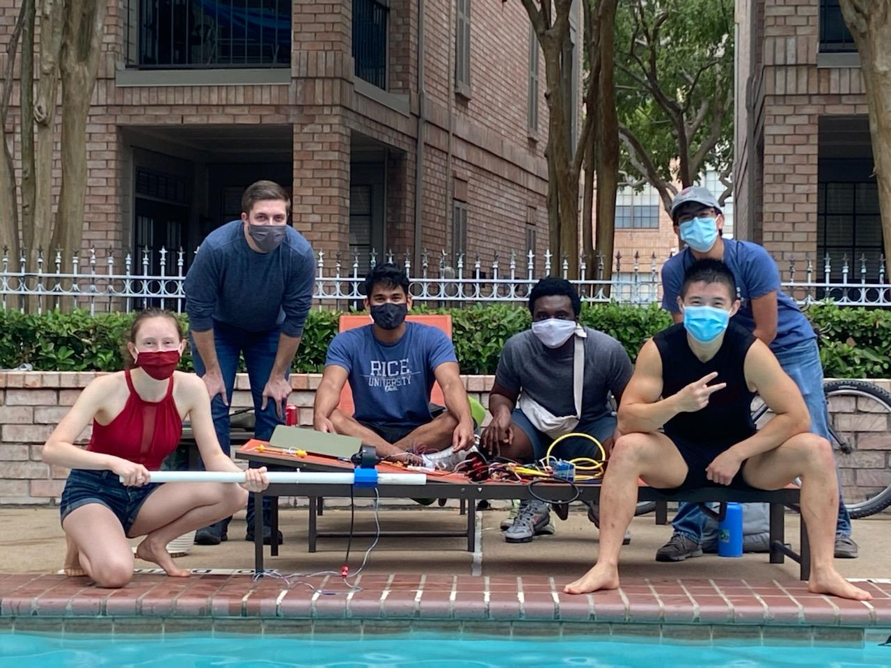
Thus Team Yeah Buoy assembled to tackle this project!
Here is a pic I photoshopped (social distancing means no group photos)
As always, project elements will be presented in mostly chronological order, with some small rearrangements to group like objects + make things easier to understand.

Supporting our group would be a handful of key individuals.
Alicia Keow, a PhD student in Mechanical Engineering at the University of Houston, had done research on buoyancy control using electrolytic cells. We consulted her many times throughout the year, and she was an invaluable resource to us.
Colin Zavislak, a master’s student Mechanical Engineering in Dr. Ghorbel’s lab, had previously modelled and simulated behavior of a system similar to what we’d be creating. He was a big help throughout our entire project, especially in the controls aspects.

As it turned out, variations of this project had already been attempted by two senior design teams, neither of which achieved success nor completion.
As part of our research and intel gathering, we had access to their previous prototypes and were able to examine them for reference.

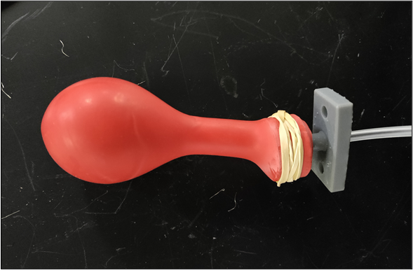
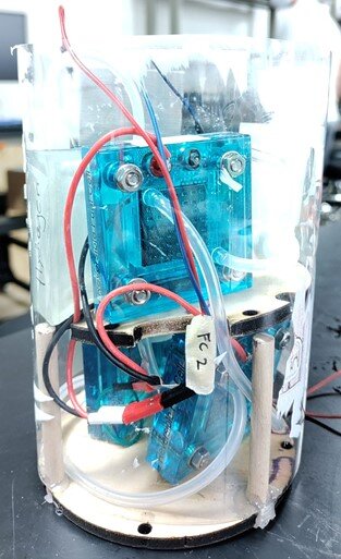
The first team was Buoybots, whose prototype consisted of simply a project enclosure with balloons attached to the side.

The interior wasn’t much to go off of: a few fuel cells strewn about, individually powered by AA alkaline batteries, and a loose, unwired Arduino hanging around inside.
We didn’t have access to this team’s documentation, but suffice to say their prototype never worked (or else we wouldn’t have a project in the first place).

The following attempt was by Team Whatever Floats Your Bot (WFYB), who as far as I can tell, never made it past the preliminary hardware selection phase.
We also learned that this setup was only assembled for a final report photo op, and even had elements photoshopped in.
Therefore, we couldn’t rely on WFYB’s design or underlying assumptions as anything proven, for ourselves to build off on.
However, we were able to harvest many usable parts from their setup, which we supplemented with our own parts.

Insights from these previous projects, combined with our own research and literature review, gave us a better understanding of the engineering problem.
With these, we drafted some preliminary target specs (yall can read, I won’t re-summarize them here)…
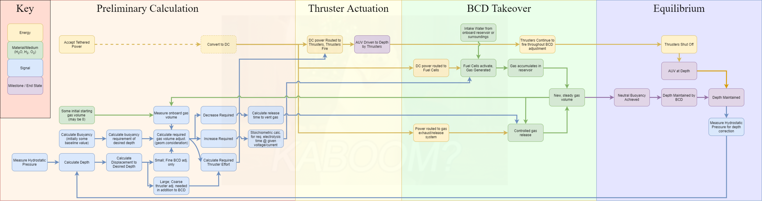
![Brian Functional Decomposition [Explicit].png](https://images.squarespace-cdn.com/content/v1/5f80fba2fa121b5b87b4bd49/1627934972914-21S8RJGARIYPRCMGEL7Y/Brian+Functional+Decomposition+%5BExplicit%5D.png)
As well as functional decompositions.
Our system would operate in 4 main stages:
Stage 1: Calculate - using sensor data and known values (system mass, volume, etc.), compute thruster and BCD efforts needed to traverse to & maintain given depth.
Stage 2: Thrusters Fire - because BCD efforts alone would be too slow, powerful thrusters quickly drive AUV to desired depth.
Stage 3: BCD Takeover - thrusters fire intermittently and at decreasing intensities as the slower BCD uses this time to ‘catch up’ and neutralize buoyancy, by generating or rejecting gas.
Stage 4: Neutral Buoyancy Achieved - thrusters shut off and AUV maintains depth with zero additional energy expenditure.

In the midst of this thinking/brainstorming/busywork phase, I urged us to begin hands-on prototyping work.
Rice’s senior design program doesn’t start prototyping until the 2nd semester (something I take heavy issue with), but from my previous project experience I knew that if we didn’t start ASAP, we’d end up with an incomplete project like our predecessors.

From a financial standpoint, we decided it would be best to reuse parts from the previous teams.
Our first step, then, was to run hardware validation tests for each component. Both in consideration of their condition as used parts, as well as part of being meticulous and doing things properly.
Even if you’re 99% sure something will work, you still need to go through and check to prevent the 1% where it fails and people get hurt.

Some key components we inherited were:
an underwater enclosure,
a pair of thrusters,
several fuel cells / electrolyzers, and
a pair of pressure sensors
We did our own benchmarking to compare measured values against advertised datasheet ones, for more accurate use in our controls model.

The first components we would test were a pair of BlueRobotics T100 thrusters.
We initially thought Team WFYB had tested these already, as we found a performance curve in their documentation.
However, that graphic turned out to be copy-pasted straight from the manufacturer site itself, so we ended up still had to do our own benchmarking.
To do this, I wrote some very basic Arduino code to manage the electronic speed controllers (ESCs).
The code basically let me command thruster speed from my computer.
(computer → Arduino → ESC → thruster motor)

Dunked it into my tub for a quick test!
Qualitatively speaking, I definitely had to exert some shoulder effort to prevent the thruster from running away.
(If my mother saw me sticking wires into my bathtub I’m sure I’d get a talking-to)

However, to get an actual quantitative measurement, we needed a real setup.
I had the idea to use a PVC rail + carriage system, and modelled it up.
(My design used airsoft pellets as bearings! They’re cheap and won’t rust)

I 3DP’ed the carriage, mounted the thruster, and lengthened the cables.
My design used a spring scale, for direct axial measurement of thruster force!
As our school pool was on a restrictive reservation system (thanks covid) that made it hard for everyone to access, I invited everyone to my apartment pool for testing!
a nice pic we took

splash


After testing, we compared our data with the manufacturer’s. The left image is BlueRobotics’ provided PWM-thrust curve, and the one on the right was our own.
Though we had no reason to believe otherwise, we were heartened to see results following expected trends! Our maximum forward and reverse thrusts reached 95.2% and 71.2% advertised values, respectively.
Thus demonstrating importance of testing / benchmarking! - if we had used the datasheet values in our controls model (later) instead of experimentally recorded ones, our system behavior could have been wildly off.

Next, we moved onto the fuel cells!
Though we mostly used them to perform electrolysis, the components we had were actually reversible fuel cells, meaning that they could run both the forward electrolysis reaction, as well as the reverse fuel cell reaction.
Just in case there was confusion from me using ‘electrolyzer’ and ‘fuel cell’ interchangeably; for our project, both refer to the same component!

These fuel cells were originally selected by previous teams, and were meant as an educational tool, not necessarily any actual engineering application.
I initially wanted to abandon them and purpose-build our own, but decided that would take too long and likely be overkill for a 1-year senior design project.
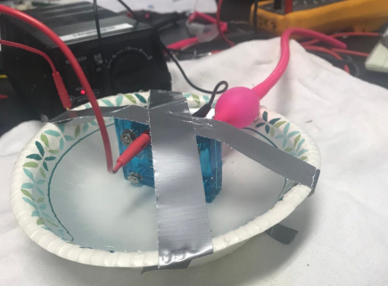
Here is WFYB’s fuel cell bank, beautifully secured using tape and rubber bands.

As the best model I could find for our fuel cells looked like this…

I modelled my own!
Continuing the electrolysis explanation from before (see my annotated CAD above):
In electrolysis, when voltage is applied to a metal cathode and anode, the energy input breaks water into hydron (H+) cations and oxide (O^2-) anions. The negatively charged anode donates electrons to the hydrons to form completed hydrogen gas, and the positively charged cathode ‘steals’ electrons from oxides, allowing them to form oxygen gas.
A proton exchange membrane allows ions to flow through and reach their respective electrodes, but prevents gas from permeating - effectively acting as an oxygen/hydrogen barrier so that both can be harvested separately!
Next, we needed some way to quantify gas production under varying conditions, such as electrode voltage, atmospheric pressure, etc.
Here was a previous team’s “test”… we could do better.
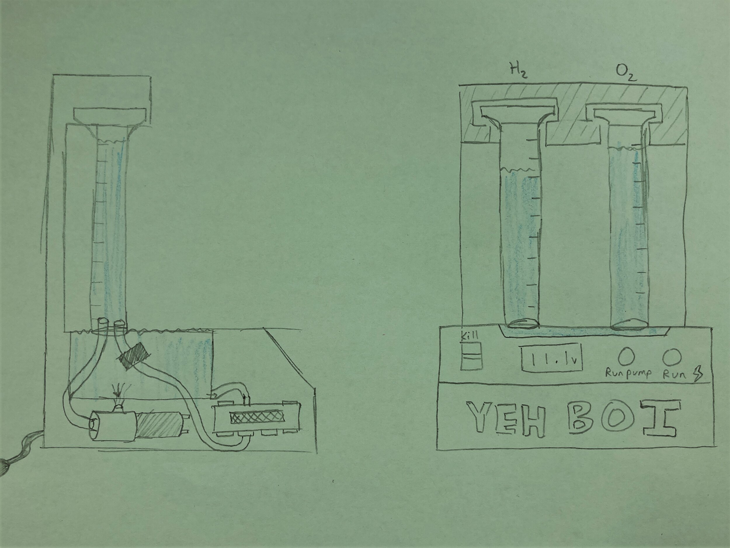
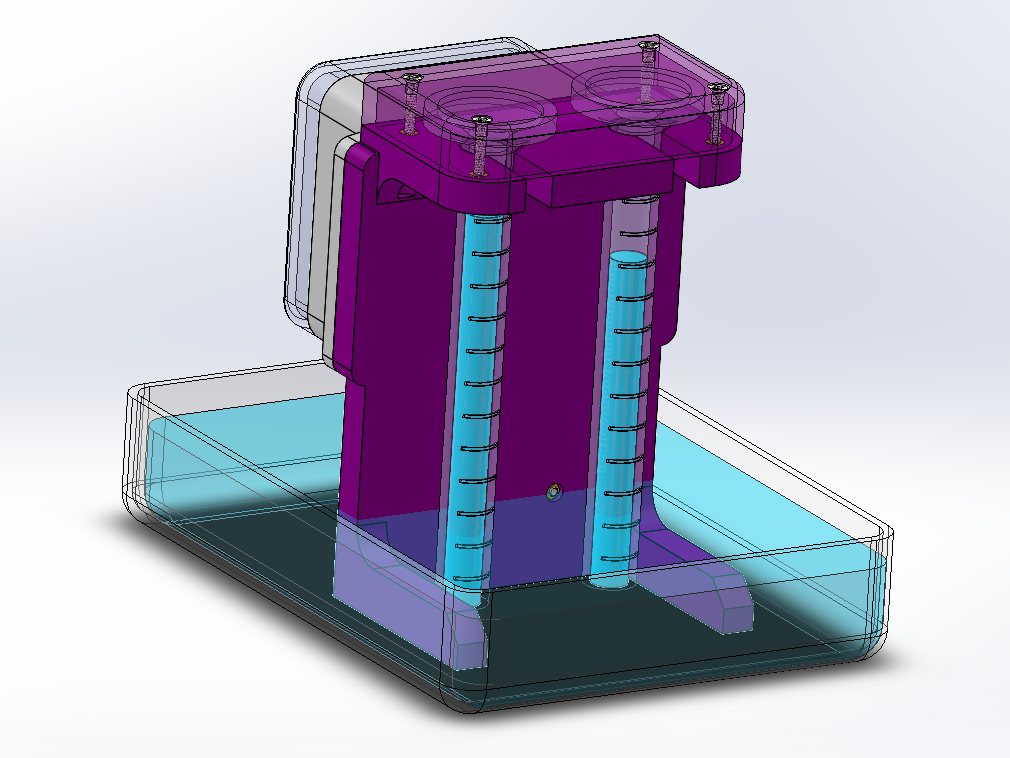
To collect and measure gas, I borrowed an idea from Gen Chem! We would use two inverted graduated cylinders to to collect hydrogen and oxygen separately, with the increment markings making for easy data collection.
Here you have the usual sketch → CAD → 3DP workflow process.
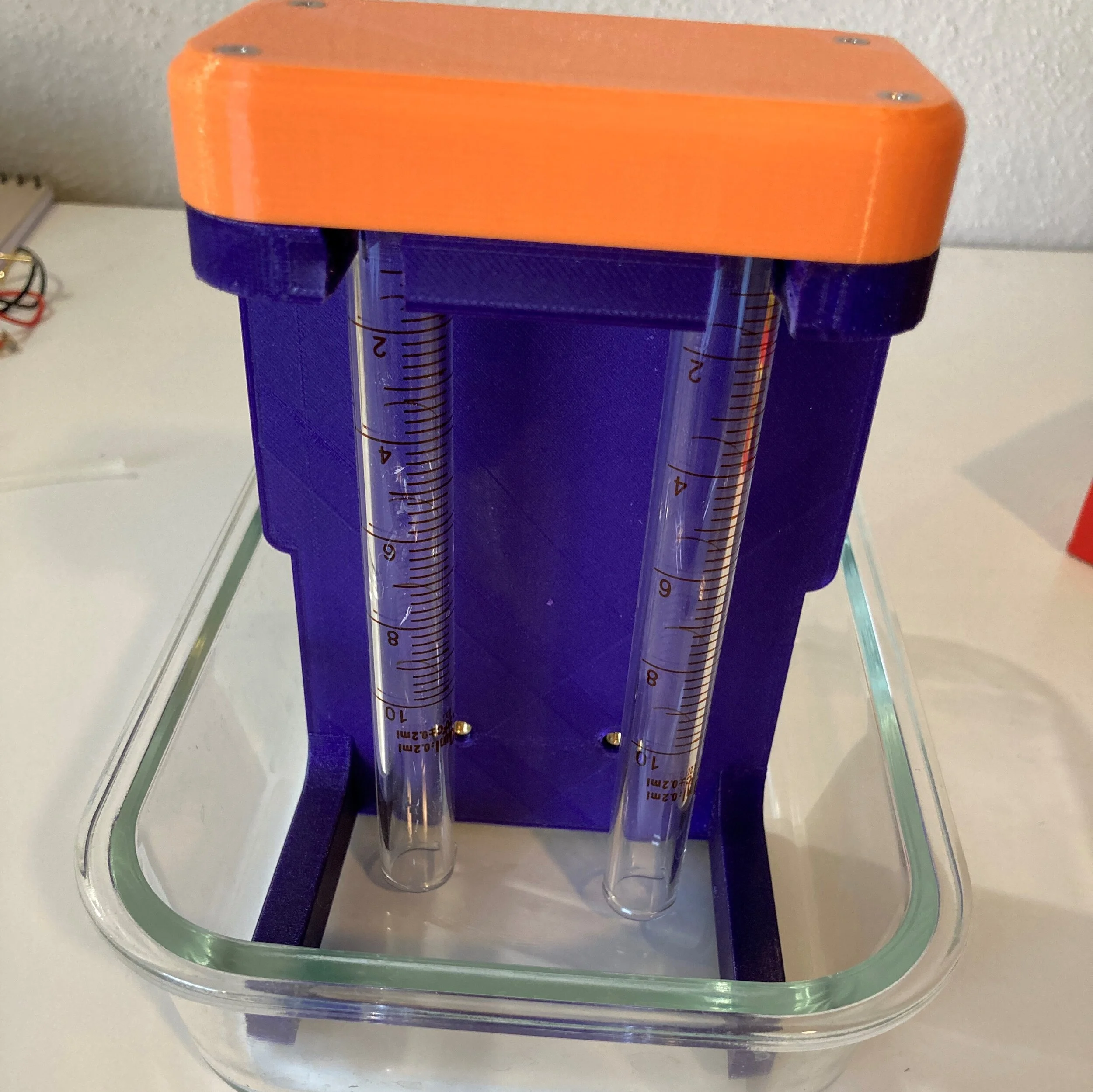
A quick bedroom test showed everything worked well, so…

We used the lab’s variable power supply to run trials at differing voltages and currents.

The addition of water reservoirs allowed us to test for longer intervals without refilling.
This element would end up being incorporated into our final vehicle as well, for longer operation time.

Using the data collected, we plotted the rates of gas production v.s. current, and found a very strong linear relationship (R^2 = 1 for both oxygen and hydrogen).
The rate of hydrogen production was also twice that of oxygen’s, something in line with the understanding of water’s chemical composition being two hydrogen atoms per one oxygen atom.

In addition to the forward electrolysis reaction, we had initially also hoped to use the reverse fuel cell reaction (consuming hydrogen and oxygen gas to create water), as a means to reuptake gas / decrease buoyancy.
While I was able to get this reaction working, inconsistency from moisture clinging to electrodes and limiting interface surface area made us abandon consumption, and settle on venting as a gas rejection method instead.
Potential solutions to this could have been a dedicated, consumption-only fuel cells to be kept dry, or a condenser tank to collect stray water vapor, but we decided against adding extra complexity into an already difficult project.

Finally, I had originally included onboard electronics (battery, multimeters, load, and magnetic switches) in the design to be able to run underwater experiments, to see whether gas production would be affected by hydrostatic pressure.
The chemical reaction wouldn’t have been affected, but there was a possibility that the amount of gas physically harvestable would.

However, though I cringed at the decision, we ended up keeping our electronics on land and running wires into my apartment pool.
We used the pool steps as preset depth increments, and used an underwater camera to record the graduated cylinders. Later review of the footage gave us our data points.
TL;DR our fuel cells displayed no noticeable change in recoverable gas volume, even at ~4 ft underwater.

After the fuel cells, we moved onto our pressure sensors!
We had inherited a pair of BlueRobotics Bar02 sensors, capable of measuring depth, both atmospheric and hydrostatic (!!) pressure, and temperature.

We decided to build a PVC water column and mount the sensor inside the base.
The test would be to incrementally add water to the pipe, and compare the known liquid volume poured in (and the corresponding water height & pressure) to sensor output data to check accuracy.
Here I mounted the sensor in a PVC endcap and am checking for leaks before cementing it to the main 4” pipe.

This was our experimental setup! Essentially a very tall drinking glass haha
If you look closely I am bleeding from my right knee, nothing unusual there

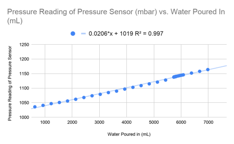
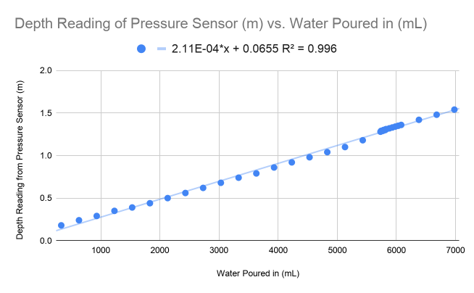
Using an Arduino, we beakered in water and read sensor outputs every couple hundred of mL.
We plotted this data and used it to verify that pressure and depth readings matched volume- and geometry-predicted values.

Finally, our ‘test’ of the underwater enclosure consisted of sealing it, dunking it underwater for an extended time, and afterwards inspecting for leakage.
Barely a test, but save for perhaps rigging the insides with humidity sensors there wasn’t a much more scientific way to do it haha

During our tests, it became clear that my apartment recreational pool was too shallow for any meaningful testing. In addition, some of the groundskeepers had started to get tired of us bringing scary-looking electrical equipment in and setting up shop.
It was time to look for new testing grounds… or waters, I guess.
Ghorbel recommended a basement pool in one of the Mech labs, but one look and I was like yeah fuck that (dear potential employers, sorry for profanity)
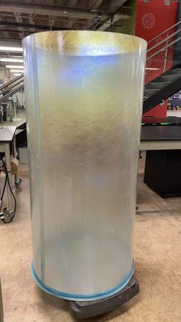

We shopped around online and bought a 30” diameter, 60” tall tank, originally meant for solar water heating systems.
The tank’s translucency would be invaluable for testing, without being prohibitively expensive like clear extruded plastics would.
We simply filled the tank with a garden hose and used an aquarium pump to drain it for storage.

With all of our inherited parts tested and functioning, our next step was to consider how to best arrange them into a submersible, as well as an actual BCD design.
Here are some sticky notes from one such brainstorming session.

With respect to vehicle design, we again looked to WFYB to see where we could iterate and improve.
In addition to a very un-hydrodynamic profile in the vertical direction (a real head-scratcher as, due to their thruster orientation, that was the only axis they could move along)… this was also an inherently inefficient design in terms of stabilization and control.
Ideally in propelled craft, best practices are to maximize the offset between point of thrust application and the center of mass, to create the largest control torque possible, for course correcting, stabilizing pendulum motion, etc.
In this prototype, the thrusters were located just above the heavy ballast (gray PVC section), directly at the average center of mass.

With those insights in mind, and taking inspiration from hobby ROVs online, I came up with a new design!

As Ghorbel specified our vehicle only needed to move vertically along the water column, I thought to orient our cylindrical enclosure, well… vertically as well.
This reduced our drag profile and allowed for more efficient movement along that axis.
I added additional steel plates to the enclosure ends, and a cage of standoffs between them for easy thruster mounting.

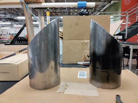
After concerns were raised about this design looking too phallic, I added in an aluminum shroud to both camouflage the shape and add some much needed mass + density to an otherwise empty cylinder of air.

Also, this might also have been vaguely inspired by the Y-wings from Star Wars, in particular the shrouded versions from the Clone Wars show.
Can you see the resemblance?

We threw around several ideas for the BCD.
I pushed particularly hard for a rigid extrusion that would telescope out of the body to increase displacement volume. I believed it advantageous over any amorphous soft bladder in that it would resist the crushing hydrostatic forces better, and make calculations easier due to the volume increase being directly linear with the extension distance! (V = A x h)
This extrusion could be actuated by a gas piston if we really wanted to keep the ‘gas’ aspect of the project, but would be even better suited for use with an electric linear actuator! Controlling an electromechanical component would be far easier than trying to control a chemical reaction, with its atoms and molecules randomly bumping about.

However, we ended up settling on external sacs (balloons) after Alicia Keow showed us a video of her small scale electrolyzer buoyancy vehicle.
I think the grad student clout won my teammates over :(

I couldn’t help but be a bit bummed. Like guys, the extrusion could have been beautiful! + Worked perfectly with the ‘rocket’ aesthetic too!
I admit it would have somewhat defeated the whole soft robotics thing Ghorbel was going for though.
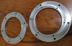
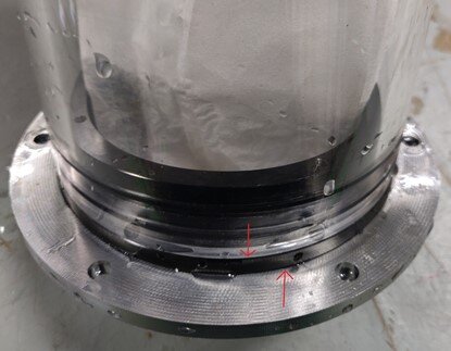
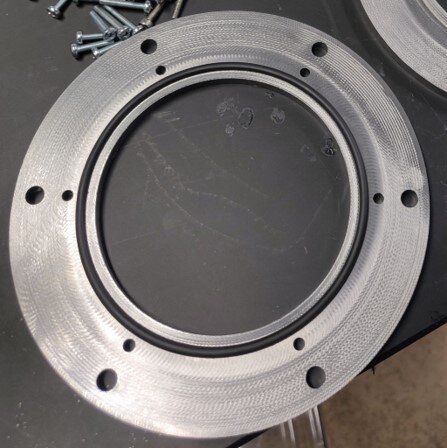
We got the two end plates machined from steel stock, but realized during testing that water leaked in through the mounting holes. So we remade the plates with an o-ring to seal things off.

As our skilled school machinist had been working from home due to covid precautions, we simplified the design down to just two side-mounted angled pipes, again to add some mass to the craft and to maintain a somewhat aesthetic profile.
The aluminum standoffs were replaced with threaded rod for adjustability as well.

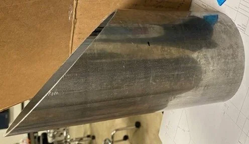
My original design had used aluminum for all external body components, both to avoid excessive weight and to prevent rust. I think there was a miscommunication somewhere along the line, as steel stock was purchased instead.
Despite my fears of this setup being too heavy, we decided to try it anyway. We used a Johnson saw to chop the pipes to size (the seam in the leftmost picture was a mistake cut that I had to re-weld), and add the angled cut!
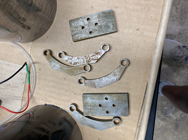

To mount the thrusters to the threaded rod cage, a teammate water-jetted some brackets out of 1/4” steel, and I welded them up.
However, as I wasn’t too happy with how they turned out, I asked for the pieces to be remade with alignment notches. You might also be able to discern the mounting method from this pic! The thruster mounts to four holes on the rectangular piece, and the large circular holes slot over the threaded rod and are held in place by opposing jam nuts.
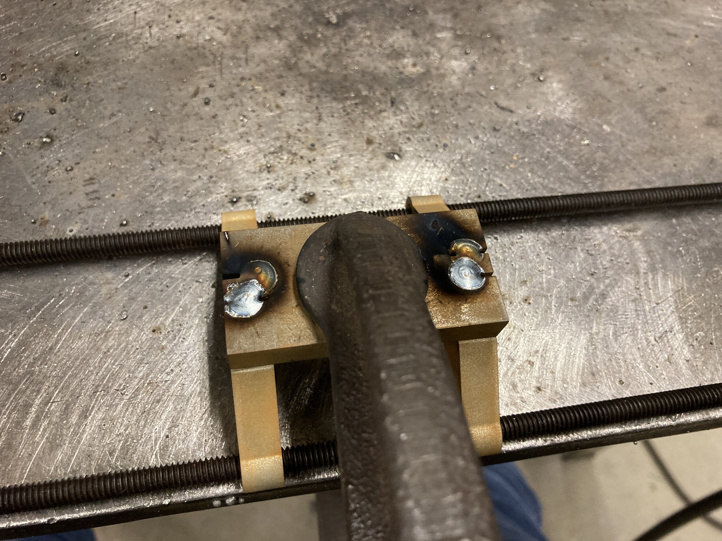
With the improved alignment tabs, I was able to weld worry-free! Just a few tacks in the photo, not a full weld-out yet.

I cut some channels into the pipes for the brackets to sit in…

… And installed them on our vehicle!
You can see the cage and mounting situation like I mentioned.

We installed the thrusters and ran some preliminary testing. Everything looked good!
In the meantime, we also worked on gas management - methods for storage and rejection.
As we had settled on inflatable sacs (balloons), we needed a way to attach them securely, and be able to pressurize them without losing gas.
We had been using syringes and elastic bands during testing, so we replicated that geometry in a resin 3DP part. We made sure to include a nipple for the pneumatic tube as well. With this system and a few one-way check valves, we were able to inflate the balloons using only the fuel cells, and no additional compressor / pressurizing element.

As previously mentioned, we had abandoned gas reuptake using the fuel cells, and instead planned on using solenoid valves to dump gas from the balloons.
The valve exhaust tubes were bundled in with our tether and released gas directly to the surface.

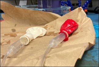
Here is our overall gas management system! Gas flows from the fuel cell bank, through the check valves, and into the balloons. Then, when our microprocessor deems our craft to be too buoyant at its current depth, it sends a timed signal to the solenoids to release some or all of the accumulated gas.

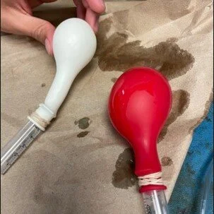
Here is a clip of the solenoids open and venting gas into the environment, and in the process deflating our ‘swim bladders.’
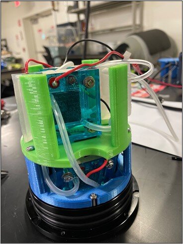
Next, we prototyped and printed a new, stackable fuel cell mount design. These could be bolted into the existing underwater enclosure end pieces, as well as to each other, in case we ever wanted to do a larger vehicle. This modular design made scaling the number of fuel cells very easy.

A clip of the fuel cells operating.
I dunno why, but this color scheme reminds me so much of old beach toys I used to play with as a kid. Is it just me?

With most of our physical systems working, it was time to develop the electronics and models to control them!
Here was our wiring diagram, with an Arduino Mega managing our components.
It’s nothing crazy; despite the conceptual difficulty of our project, we didn’t actually have that many components to keep track of.
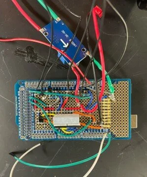
From left to right:
An Arduino Mega hiding under a Shield with power electronics,
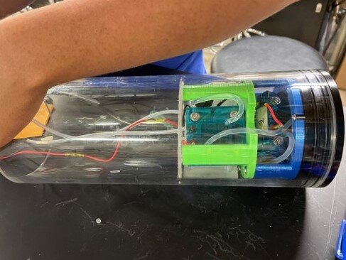
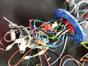
Our end plate, finally populated with cables and hoses. For the most part our electronics just free-floated inside the vehicle casing. We were definitely running low on time at this point, and you can see that reflected in our wiring ¯\_(ツ)_/¯
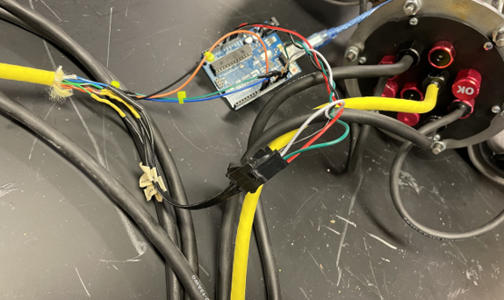
A poorly-framed picture (my bad) of the plate exterior, and its various cables running through waterproofed penetrators.
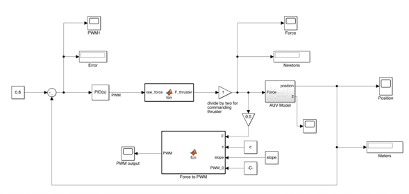
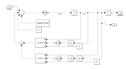
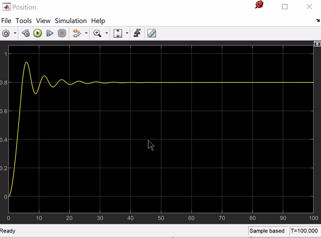
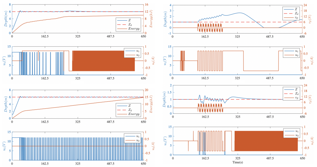
To control the craft, we had initially hoped to use PID (Proportional-Integral-Derivative) control, and drew up some Simulink block diagrams to simulate BCD behavior.
The left and center diagrams represent the thruster and gas systems, respectively, and the right was a simulation of the AUV’s depth position as it would travel to and settle at a depth. We ‘optimized’ (lol) using trial-and-error to find values that would yield the quickest time to target and the least amount of oscillations / bobbing, to eventually import into our Arduino code.
However, we eventually settled on separating the control schemes into PD control for the thrusters, and a simple on-off scheme for the fuel cells. It was very late in the semester and we thought this the most realistic solution given our timeline.
Also, huge credits to Electronoobs (in particular this video) for being a great resource on actually implementing control laws in microcontrollers. Despite the many controls problems we did throughout undergrad, we were never taught any programming implementation - a huge flaw in the curriculum if you ask me.
Here is a quick test of a simple P (proportional) control law, before we added in the derivative portion for full PD control.
We used an ultrasonic distance sensor as a stand-in for the depth sensor for testing on land, as the operating principles were the same.
Basically, the farther the sensor data deviated from a target value, the harder the thruster would compensate to return the system to that value.

Also, no surprise there, but our heavy steel structures made our vehicle too heavy for the thrusters to lift, and repeatedly sank during trials. We removed the shrouds.
Also, we had moved the thrusters from their position atop the vehicle to closer to the bottom.

This was a poor choice on our part, and I’m still not sure why the change was made. Especially as it was this exact flaw in WFYB’s design that I had originally redesigned to eliminate.
As is usually the case in air/watercraft design, positioning the load / center of mass below the point of thrust (~ pivot) creates a self-stabilizing pendulum situation, where even if the craft is offset by some angle, components of gravity acting on it will help restore its original orientation. This is highly desirable, and something my original design accounted for, as you can tell from my pretty picture on the left.

However, what our new design created was essentially an inverted pendulum, an example of an inherently unstable system. As you can tell from the force diagram, an inverted pendulum offset by the same 25 degrees as the regular pendulum above will not restore itself, but rather swing and fall due to the gravity components.
Even though this diagram doesn’t account for the segment of vehicle still below the thrusters and pivot, the majority of the load remaining above meant that the center of mass was as well, still qualifying this setup as an inverted pendulum.
It’s funny - if you imagine the natural progression of this swing, you’ll see that the vehicle actually returns to a thrusters-on-top orientation, like my original design. Even without a free body diagram, you are able to intuit which design would exhibit greater stability (and really should have been kept).

Again, there is a reason why every conventional rotorcraft in existence carries its payload below its thrust plane.
In any case, our test trials with this setup were successful, so I suppose there was nothing to complain about.
Although I do think this was an instance where the numbers happened to work out - our thrusters were strong enough for our particular vehicle, and we didn’t test any extreme angles.
We were lucky this was only expected to work as a proof-of-concept in a test tank; it probably would have toppled in any open body of water.

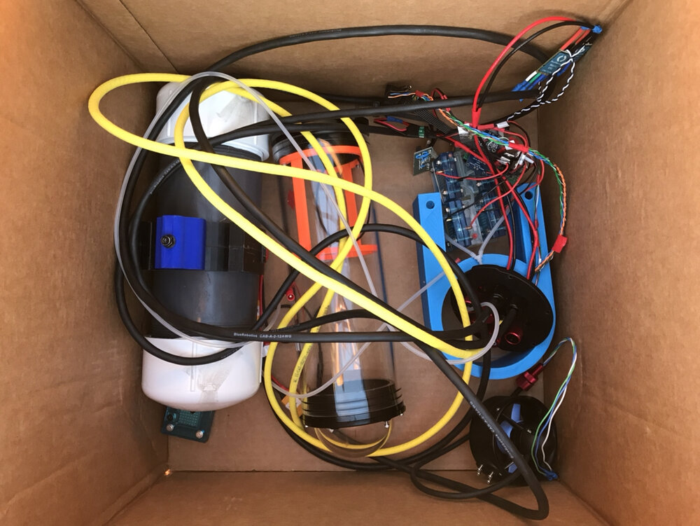
After that, we installed our balloons and very elegantly… shoved our electronics inside.
Desperate times call for desperate measures 😤

New coat of paint though! Definitely made things look nicer.
Here is a video we took of the gas system as installed in our vehicle.
Going through a full gas generation fill cycle, and then venting all of it through the solenoid valves!
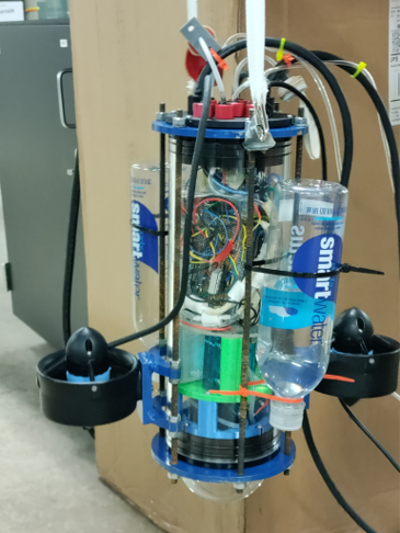
Finally, in order to ‘gain back’ some of the mass lost in discarding our shrouds, we zip-tied water bottles to the exterior cage.
This let us easily adjust their fill level and amount of mass attached to the vehicle, to tune it for close-to-neutral buoyancy (the closer we were to that mark, the less work the BCD would have to do).
Again, desperate times call for desperate measures 😤
Here are some clips of our final testing.
TL;DR: All systems were go, PD control successfully brought our vehicle to set depths and held it there, as the BCD balloons filled to match.
YUS!


While I didn’t think our project was anything fantastic, it impressed enough people to win the Willy Revolution Award for Outstanding Innovation at our end-of-year Engineering Showcase!!
It’s actually pretty funny, I had already tuned out of the Zoom call and gone to the gym by the awards ceremony, as my attention span was long extinct by that point. But all at once, I got a bunch of congratulatory texts from friends, and it took me some time to figure out why 🤣

Oh yeah we also won $3K too, that was nice
No, not each - I wish

But yeah, thanks for reading!