
Breakthrough Automated [K]annon Instrument (BAKI)

In my ongoing campaign to become a walking, talking Mobile Suit, after I finished the S.A.G.A. (Superior Assault Gauntlet Apparatus) project for my forearms, I decided the next body part I would ‘weaponize’ would be my shoulders!
I wanted to create a camera-equipped shoulder cannon that could track, lock on, and fire automatically, like a Gundam!

Before I dived into a full-blown shoulder cannon project, however, I thought it best to do a practice run first.
I knew this was a bonkers project, and didn’t want to make the mistake of rushing in, blowing a ton of time and money, and ultimately realizing I was in over my head.
I thought doing a simpler project first, like a stationary turret, would let me develop and iron out key systems for ease of transplant into a following, full-spec project.
The problem was, the only languages I had ever programmed in were MATLAB and C++, both for very simple applications.
An autocannon would surely be much more complicated, so I enrolled in ENGI 301: Practical Electrical Engineering to learn Python and power up my electrical & programming skills.

The final assignment for ENGI 301 was to create an embedded system, with previous projects being super basic, like a noise-activated LED or a temperature display 😏
I imagine everyone thought I was such a tryhard when I presented my proposal, for a straight up camera computer vision auto-tracking turret. This was above the level of most senior design projects even, and while I was aware of that, I still wanted to challenge myself and learn from it.
Without further ado, this is:
project b.a.k.i. – breakthrough automated [k]annon instrument.

Though b.a.k.i. is ostensibly just a hamfisted acronym, it’s actually the main character’s name in the manga Grappler Baki! It’s a frankly bizarre show, where a cast of martial arts-obsessed weirdos beat each other up for fun. Highly recommend 👍👍
As always, I’ve organized this writeup in mostly-chronological order, with minor changes for flow and clarity:
(Yes, that is Baki squaring up against a giant praying mantis 😂)
Raspberry Pi + OpenCV
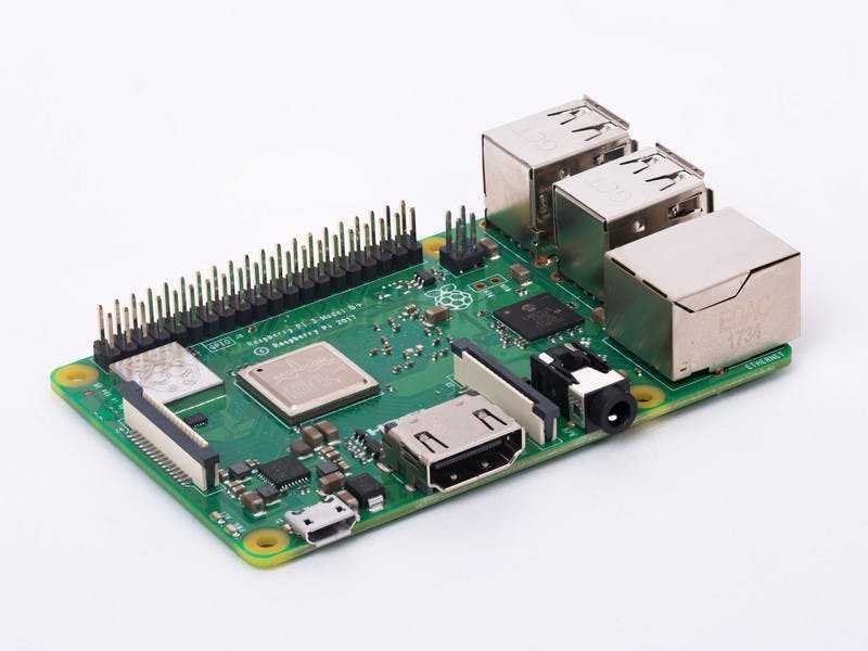

Despite our instructor wanting us to use the Pocketbeagle microcontroller, I declined (🤡) and used a Raspberry Pi instead because of its faster processor and larger RAM, more documentation, and it being more useful on my resume.
Both the Raspberry Pi and Pocketbeagle’s OS were based on Debian Linux, so while I may have been a little rebellious in disobeying my teacher, most of the things we learned in class could be mapped directly over - so no harm done!
This added computational power was absolutely critical for my project, because computer vision is a very resource-intensive task.
Speaking of which, I selected OpenCV (Open Computer Vision), an open source library (like a prepared code toolbox) to handle those tasks, because it paired well with Python and there was documentation readily available for it.


This was my workspace!
I had very little space in my dorm, but I made the most of it by borrowing a TV to use as a monitor, and laying a plank on a crate to use as a table. There’s a dumbbell weighing everything down 😆.
At one point I was worried that the Pi was throttling its processing speeds from excessive heat, so I put a bag of ice underneath it XD.

With my workspace and Pi ready, it was time to download and build OpenCV!
After grabbing various dependencies using sudo apt-get update and upgrade, and downloading OpenCV via pip install, I had to compile it using make -j4.
This took a looong time. The Pi would repeatedly freeze and I would reboot it.
After more research, I realized that I had too much RAM allocated to the GPU, and not enough to the CPU. I also needed to increase the swap size from its default 100. That sped things right up!
Eventually, OpenCV did finish building, and words cannot express how happy I was!
After spending some time in Python and OpenCV (and many YouTube tutorials), I was able to get the Pi to read and manipulate video from a webcam.
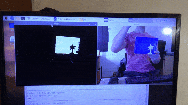
Here is a good demonstration of the targeting method I decided to use. Using a specified HSV color range, the program would block or ‘mask’ out anything not in the range, and the remaining colored patches would be target zones for my cannon.

The Python script I wrote first finds the coordinates of the centroid of the color mass, and the x- and y- distances from the center of the camera frame.
Based on this, it issues servo motor commands to turn the camera and cannon on two axes until the target is within a certain distance from the center.
During debugging, I had the camera feed displayed on my computer via remote access, and I superimposed some lines over it to act as a targeting guide.
preliminary Electronics work

After getting fairly reliable results from OpenCV, it was time to add servo motors, to be able to move the cannon!
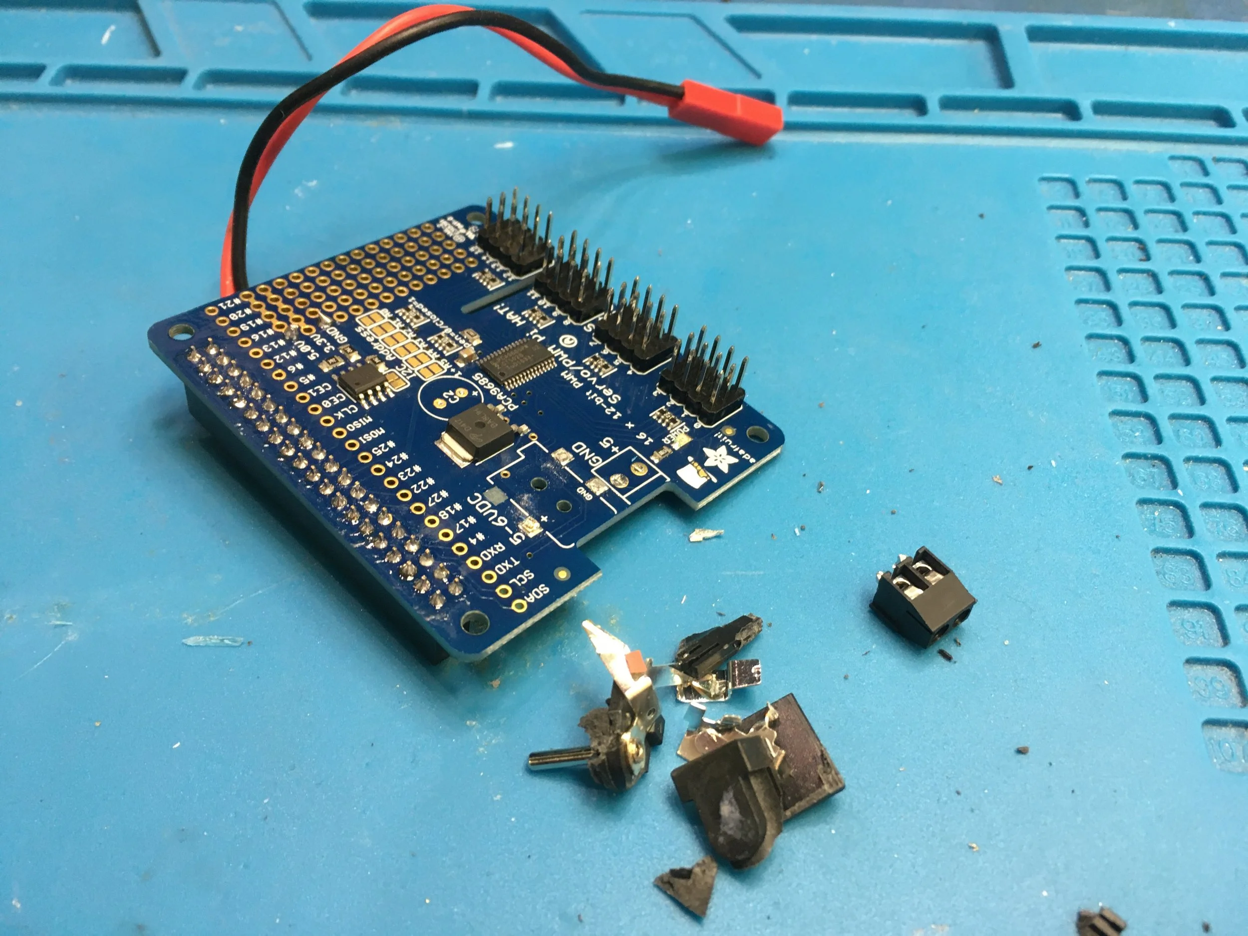
To do this, I bought a Servo Controller Pi Hat, a plug-in peripheral that allowed the Pi to control servo motors directly.
I removed the barrel connector and remounted the capacitor underneath the Hat to make things a bit more compact.
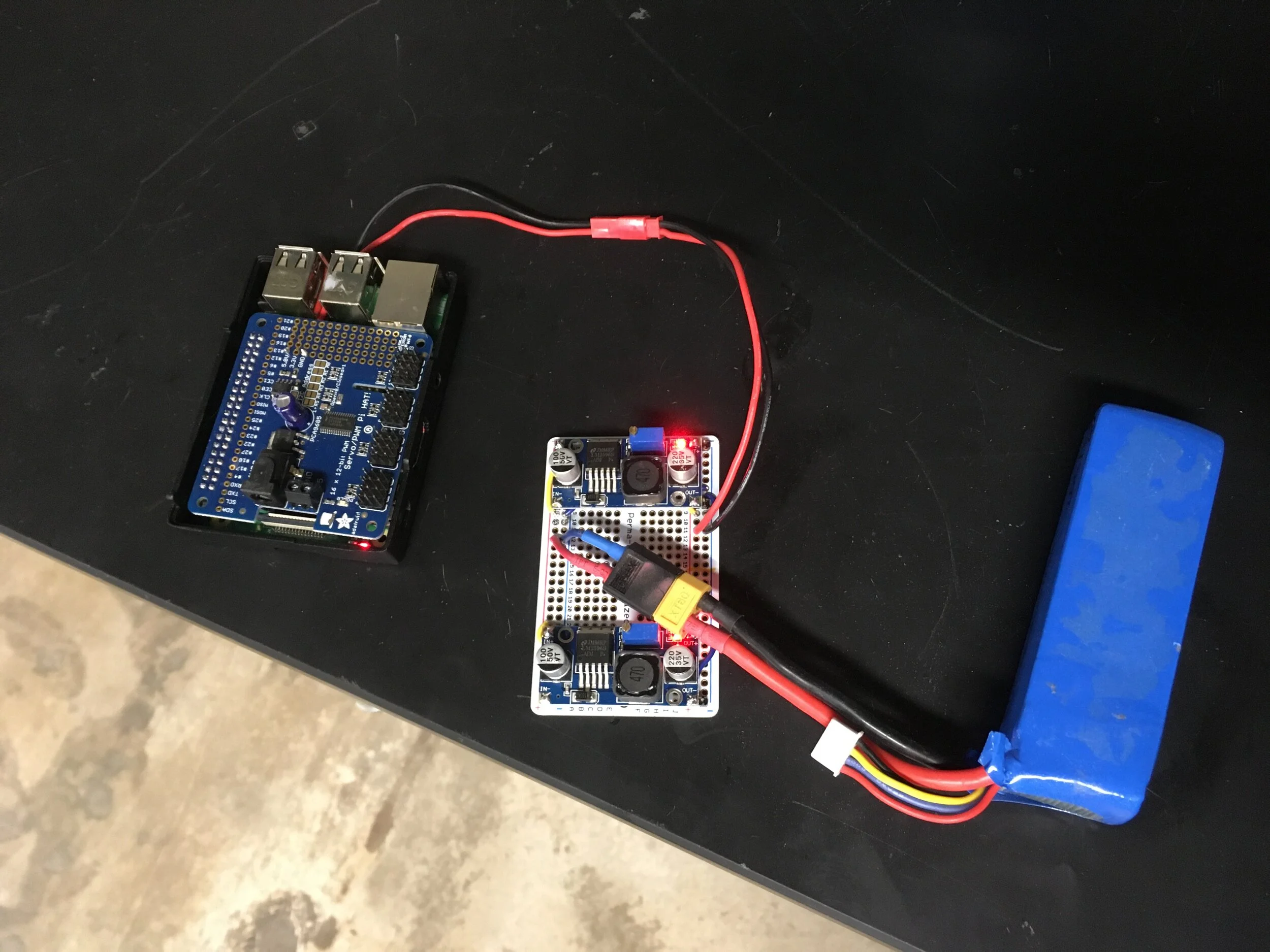
To power everything, I used a permaproto breadboard and buck converters to make a power management board.
This let me power the Pi and servo hat from an onboard Lipo battery!
In addition to the wall adapter not being to supply enough current to my servos, this decision meant that b.a.k.i. could operate anywhere, without needing a nearby outlet!

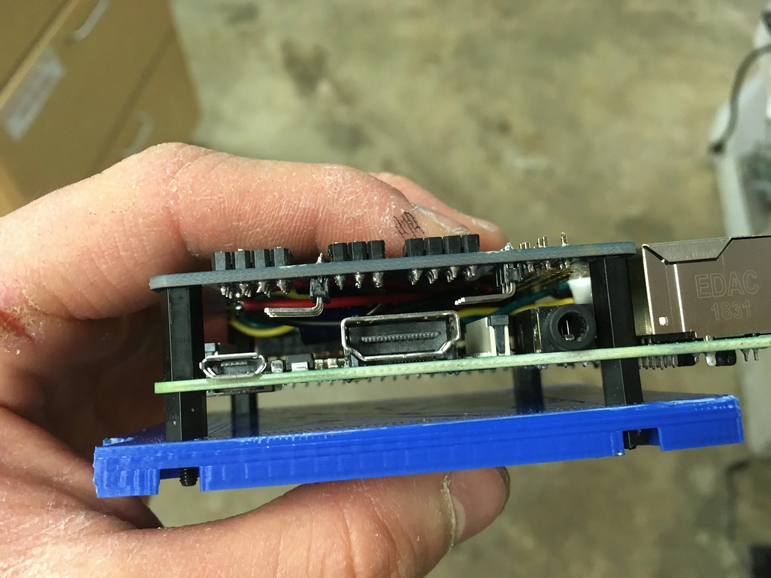

Here are the Pi and servo controller stacked on some nylon standoffs and bolted to a 3D-printed plate.
(1) Whereas usually the servo cables are attached vertically via header pins (circled in red) atop the Pi Hat…
(2) By trimming them all and soldering in new 90° header pins below the board instead…
(3) I could attach the servo wires parallel to the underside, saving ~1cm of height and making things drastically more compact!


Here is the electronics ‘sandbox’ I tested everything in, and the servos I’ve been talking about this whole time, cycling.
Nothing too interesting, but part of the documentation nonetheless.
(I find it hilarious how the only part not being used in the 1st picture is the breadboard 😂)
fabricating cannon components
With a now mostly-working electronics loom, it was time to design some physical components!
Though some back-of-the-envelope calculations suggested my servos would be strong enough to move everything, the only way to be absolutely sure was to physically build and test everything!
I also needed to figure out how I would mount the electronics, camera, motors, and battery. Having a physical prototype would help visualize that problem immensely.


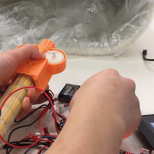
The system I planned on using to fire Nerf balls from the cannon was actually a direct import from my SAGA project, just with a longer cosmetic barrel and smoothed lines instead of the previous angular aesthetic.
It uses flywheel friction to grip and launch foam balls. A good analog for understanding would be a baseball pitching machine!


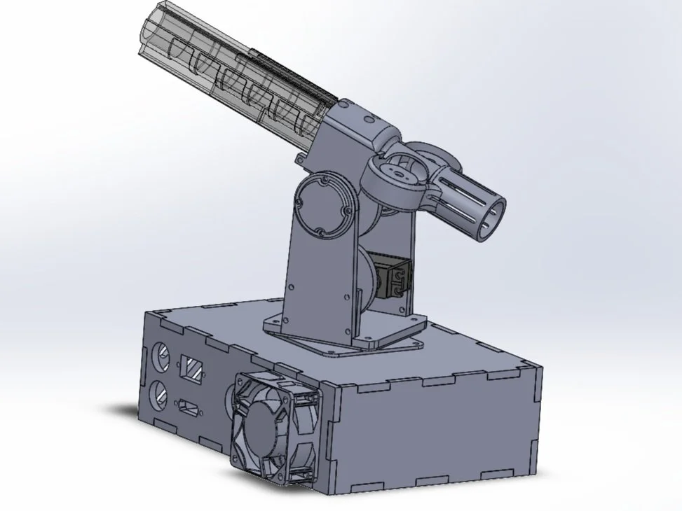
Here is the progression of my design, from sketch to early model, to final model!
I’m good at conceptualizing designs on paper, and oftentimes skip the CAD step entirely before starting fabrication. This time, however, Solidworks helped me visualize how to best arrange and assemble those pesky few components I wasn’t sure about.
Basically, my design consisted of a base, a turntable, a pair of field goal-like uprights, and the aforementioned flywheel system.
The base / enclosure houses the Pi and auxiliary electronics, the turntable enables horizontal rotation for cannon panning, and bearings housed in the uprights allow for vertical tilt rotation! The flywheels handle the actual shooting, as previously mentioned.
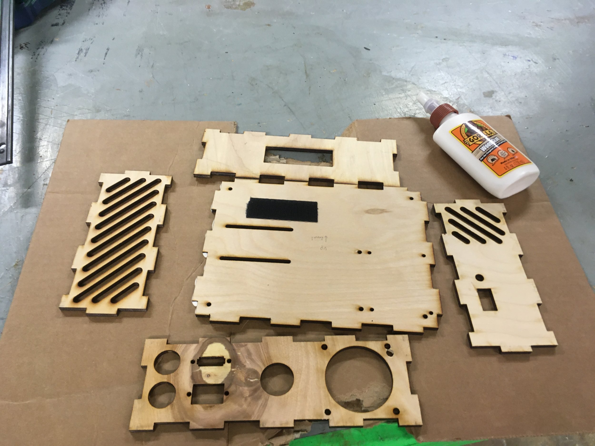

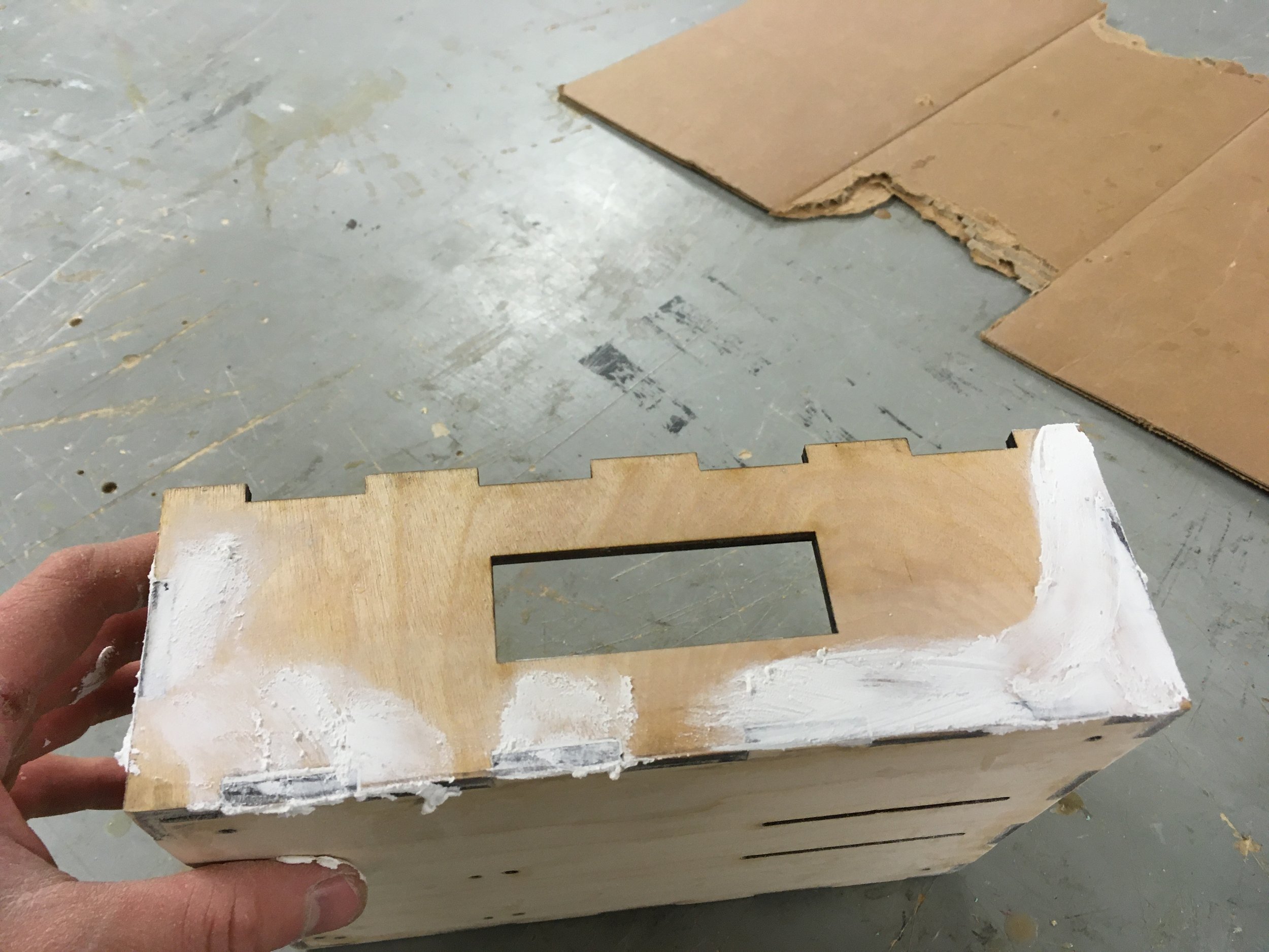
Using a laser cutter, I made wood panels to form the electronics enclosure & base for the cannon.
I included decorative (semi-functional??) vents, as well as holes for switches, plugs, and displays to sit though.
After gluing the panels together, I applied body filler to hide the joints. Just to make things look that much more polished 👌🏽.


I also designed the bearing mounts to be laser cut panels, and threw in some decor while I was at it!
By painting the wood black before laser etching it, I was able to get a ‘negative film’ effect of Baki flexing, and print the project name in block letters on the top panel.
It looks so freaking goodddd 😩
Gear Drives
Next, to properly enable my cannon’s 2-axis horizontal/vertical targeting,
I needed to think about how to take the servo torque and deliver them to the proper parts.
I went about this by using 2 gear trains!


To ensure parts would rotate smoothly with motor input, I went looking for bearings and turntables (basically a bearing with flanges).
Though I was planning on sourcing a turntable from the workshop part bins, no matter how much I rummaged, I couldn’t find one!
Had a mild panic attack until, on a whim, I climbed a chair and found one on top of a high shelf. It felt like a real life easter egg!
I bolted the turntable to a black 3D-printed cannon platform, and the two wooden bearing mounts to flanges on its side.
The gray gear on the bottom bolts into the black platform, and does so with a square taper for torque transfer. It links to a complementary servo-mounted gear for horizontal panning. I’ll cover the vertical panning in a later slide, but…
Key takeaway is — with all the elements described, this one subassembly can account for both my axes of cannon rotation!
(I know that might have been a lot, sorry!)


Onto the vertical rotation aspect: I found some gears online, 3D printed them, and epoxied them to my servo horns.
In addition to the flywheel cage I made earlier, I also made a geared shaft for it to sit on, that also slides into the bearings.

To note — The reason I’m using gears at all, instead of axially mounting the motors in line with moving parts, is because I was trying to avoid having the motors themselves be load bearing elements. By having the weight of the moving cannon parts supported by their own shaft and bearings, and having the motor solely responsible for torquing it, I could minimize motor wear and maximize lifespan.
In any case, the gears mesh beautifully and do their job well!

After that, I hooked everything up to the Pi and ran it through actuation cycles.
Clean!
Electronics + Packaging

Next up was to figure out how to arrange my components to fit inside the box.
As you can see, I had accumulated a lot of flat circuit boards that had a lot of area but not much height.
This was an inefficient use of space, so I decided I wanted to stack the power management board (bottom left) on top of the RasPi / servo hat combo.


Stacking!
While the Pi and Pi hat were designed to with each other in mind & fit together well… The permproto boards weren’t, so I had to cut one down and make a custom mount plate to get everyone playing nice.
I routed the necessary wires between different layers of circuit boards. This was pretty challenging; I made sure to leave enough slack so that I could ‘unfold’ the boards and make modifications if need be.
I added some rainbow jumper wires to the top board! They’re not actually connected to anything, but add to the a e s t h e t i c 🌈
Finally, I bent the MOSFETs into a V-shape, because I am a car nerd and thought it would look like a V-block engine 😅
But yeah! Here are all three boards (five if you count the 3D-printed ones) stacked!

Here is my switching area. The green circuit board is a voltmeter, the piece above that with 6 black wires is my charging port, and the two switches in the right corner switch on the main and auxiliary circuits.
However, when I was testing for continuity, I noticed that the voltage after the switches was only 10.2 volts, when a fully charged 3S battery is 12.6 volts. There was some parasitic resistance inside the switches, meaning my motors couldn’t get their full 12V and really go wild. This was a problem.
To fix this, I added another MOSFET board in the switch area. The main switches now only control on/off logic, they are no longer part of the main power supply ‘line’. Ideally I’d find some better switches, but I was out of time.
All the JST connectors are so I don’t need to cut and splice in replacement parts if I ever need to swap anything out.

As the rotating mechanism was mounted on the lid of the box, and the horizontal rotation servo on the inside of the box, it was difficult to get a perfect gear mesh by just jamming the lid on. I came up with a pretty clever solution.
I mounted the servo on a bracket, and cut slots into the floor of the box so that the bracket could slide.
The process would be to (1) slide the servo out of alignment as (2) the lid and its gear were put on, and then to (3) slide the servo back into place to mesh with the now secured top gear. The ‘feet’ on the bottom of the casing allows the bolts to protrude beneath the bottom of the box proper.
Camera Integration
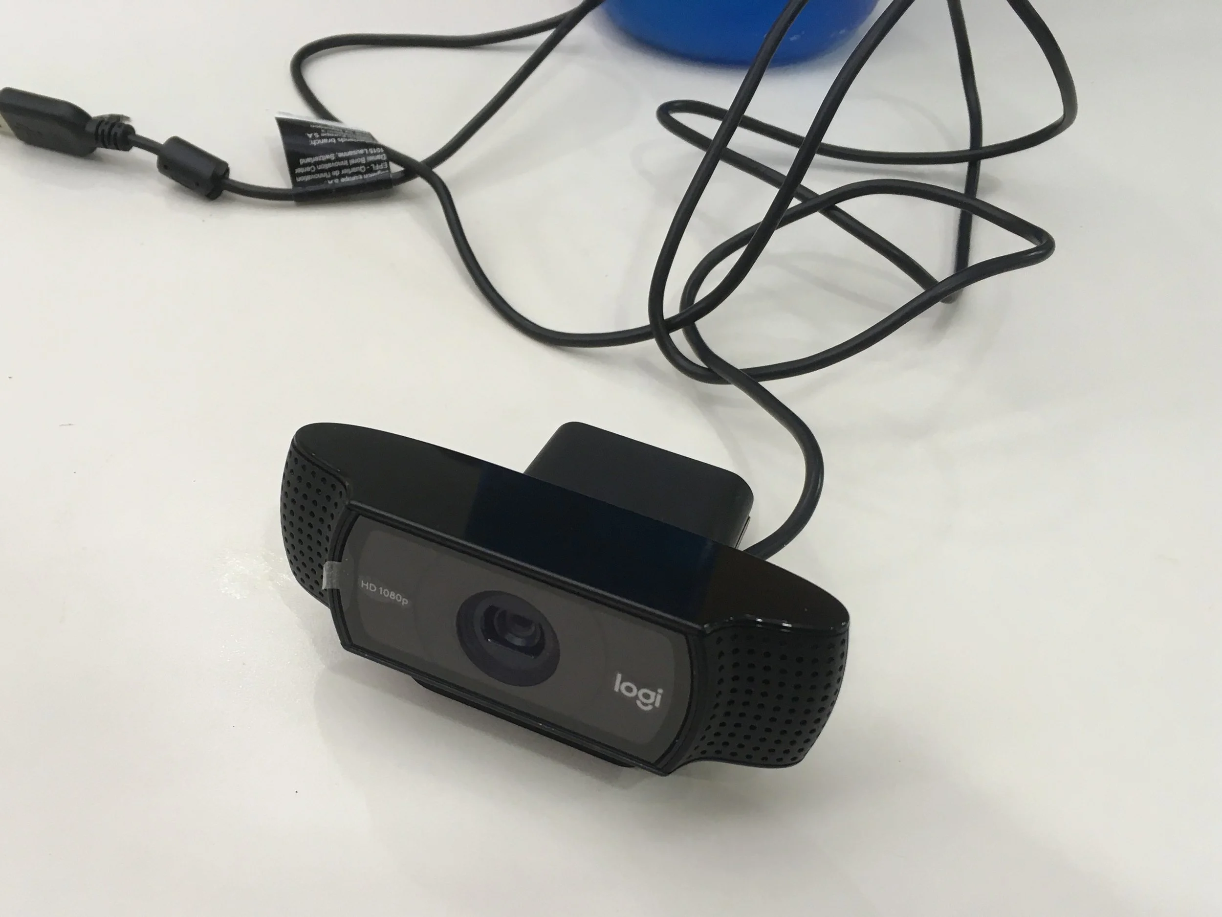


Finally, it was time to mount the camera (Logitech C920 webcam)! I left this task until last, because I was pretty sure I wanted to disassemble the camera and rehouse the electronics in a smaller enclosure.
I didn’t want to disassemble it too early in the build, and have it sit around exposed to potential damage.
In the end, all that caution ended up being pointless because I just hacked away at the case with a dremel and snips until I had the circuit board extracted.
There was a very nice disassembly guide on iFixit, but the workshop didn’t have any screwdrivers small enough :(


The webcam has these 4 cool blue LEDs that, when exposed on a naked PCB, make the cannon look really menacing.
After I extracted the camera board, I test mounted it with a piece of cardboard, taped to my flywheel cage.
Once I was happy with fitment, I modelled the cardboard strip into a more robust 3D-printed ledge, threw on some black spray paint, and epoxied everything together. (The rubber band is there temporarily, to secure the bottom end as the epoxy cures)
On my computer screen is the camera / barrel view, as well as an anime girl playing guitar apparently!

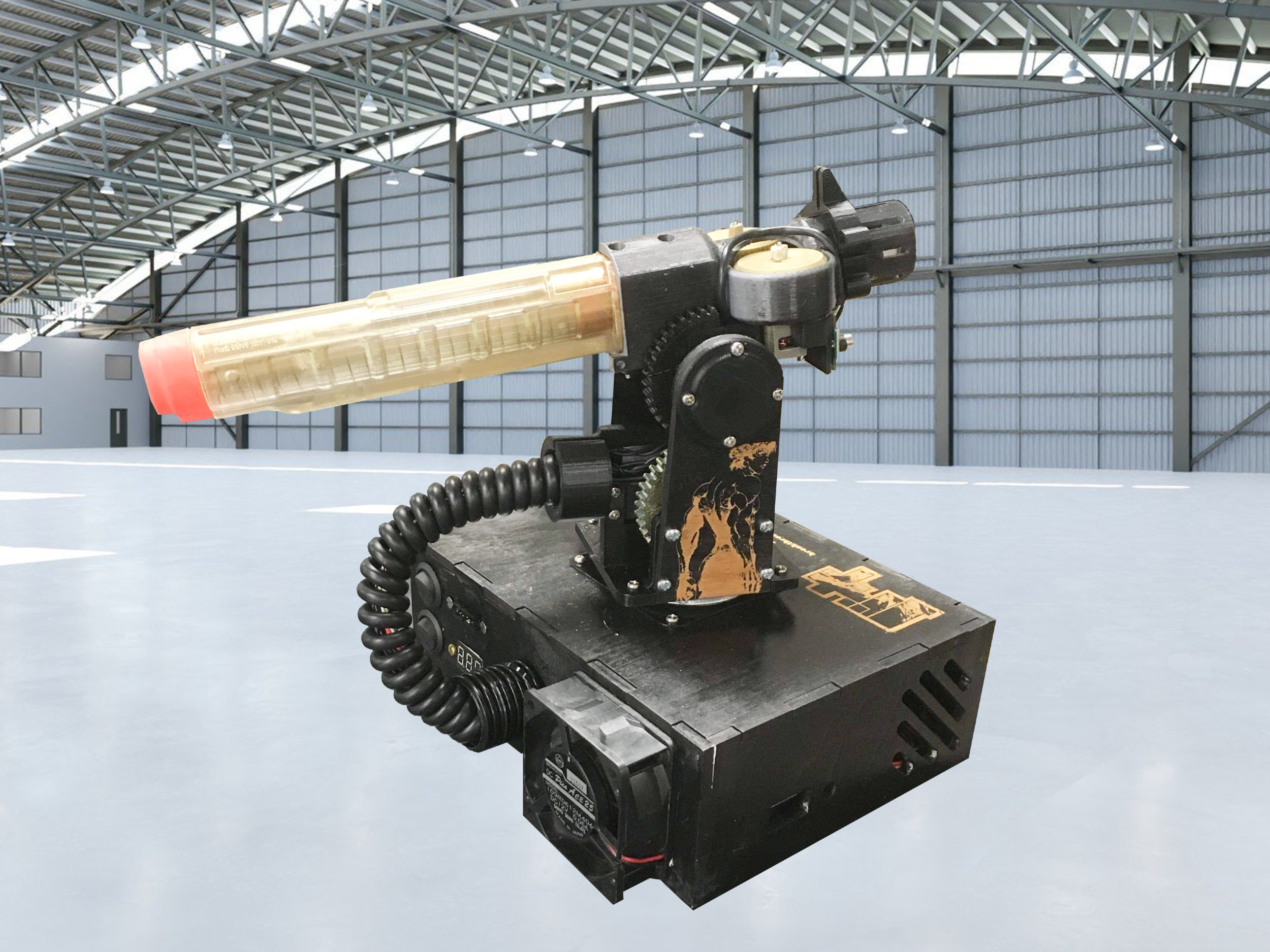
Completed ‘business end’ subassembly with: camera mount epoxied to flywheel cage, camera epoxied to its mount, motors fastened using M2 screws, flywheels painted gold and pressed onto the motor splines, and an additional cosmetic piece to fit over the barrel. It looks like a spaceship!
The gif is a clip of my cannon panning, and a perspective view of the what the computer vision program sees during that movement!
final Assembly
With all of my so-very-painstakingly crafted systems tested and working, it was time to put it all together.
I used my Kronk meme in the last writeup, so I’ll show restraint and not use it again


After carefully installing my stack of circuit boards, the horizontal sliding servo, and the lipo battery, I used zip ties to keep the wiring relatively organized.
I velcroed the battery to the floor of the box so it wouldn’t slide around, and added a spiral wire sheath to protect / ornament the cables leaving the enclosure & running to the cannon pod itself.
I left a hole in the wall for an HDMI cable too! Just in case I want to use the Pi as a computer, and watch youtube or something.
Finally, I added a bunch of green LEDs to the interior to give it that radioactive green aesthetic. Had to do it


Some more close ups!
I painted the gears gold as well, and together with the wood looking gold-ish, I think it paired really well with the black paint job.
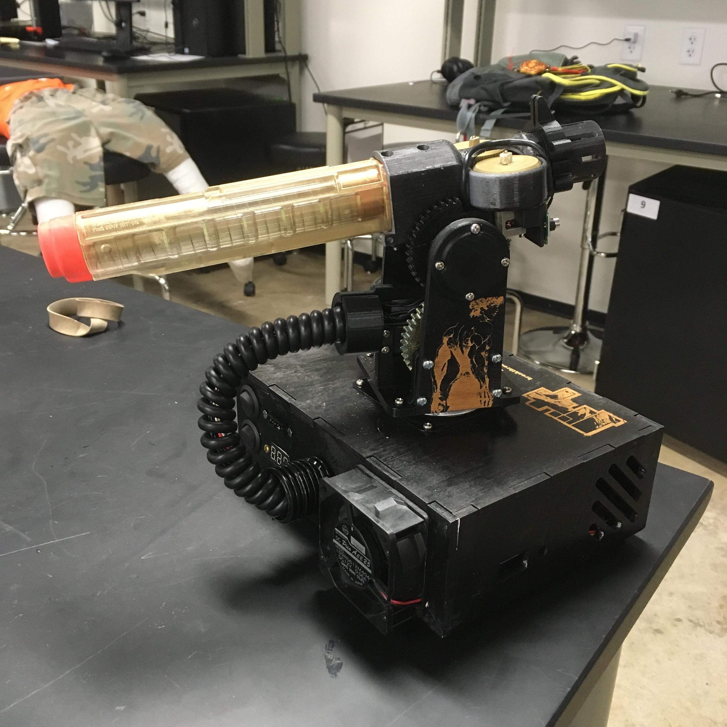

When the project aesthetic comes together just right ✋😔👌
(I said no Kronk meme but I never said no Pacha meme 😎)
testing, testing

After final assembly came one last round of testing. Here is b.a.k.i. cycling through its full range of motion.
I eventually throttled down the movement speed for actual tracking trials, due to the Raspberry Pi lagging under the heavy OpenCV RAM requirements.
The program wouldn’t realize in time when a target was already in its sights. It would continuously overshoot and reverse to try and overcompensate for rotating too far, and the solution to that (short of implementing PID control in a programming language I had so far 5? days of experience with) was to slow the servos so the program had more time to react.


*cue Wild West staredown music*
Here I am testing tracking with one of the many cans of Monster I had throughout this build.
I have the HSV range set to that particular shade of pink, and the masking program blocks everything else out to target it.

Successful tracking trial!
I should mention that at the time of writing, b.a.k.i. does not fire. The code for it to fire does not yet physically (virtually?) exist. That is intentional.
The OEDK has gotten upset with me (😠) in the past before for building Nerf blasters in their facilities.
Therefore, I am waiting until I have b.a.k.i. built to a degree that it can run indefinitely without OEDK maintenance before I add in the last lines of code to enable full functionality.
That way, I can claim it technically isn’t a ‘blaster’ in that it cannot blast anything 😈
Otherwise, all of the hardware (all three motors and wheels, MOSFETs, and Zener diodes) are installed and ready for action.
next steps
As project b.a.k.i. is a stepping stone project for the full-spec Project B.A.K.I., the things I learned here will definitely be carried forward. Improvements I am hoping to make for the full shoulder cannon are:
Rotating barrels
Optional joystick override control (via Wii Nunchuk and SPI)
Remote keyboard access for another user to operate cannon as it sits on my shoulder
Instead of a 7-round magazine, implement a tank of Nerf balls and a blower air delivery system for sustained fire
Brushless motors to drive flywheels (higher performance, and I want experience using ESCs)
Preprogrammed firing patterns
Add a third degree of freedom by having the turret ride on a sliding stage up and down my back
Addition of Real-time Clock to Raspberry Pi
Optimize OpenCV further to reduce lag
Introduce better cooling system to be able to further overclock Pi
Just to name a few.
Conclusion (what is this, a high school English paper??)
This project definitely taught me a lot! By setting the bar high and rising to meet it, I learned much more than I would have by doing a safer project. I’m absolutely ecstatic about how everything turned out. I got an A in that class too, so that was nice.
Thanks for reading!