
Dance Dance Revolution

For the final project in our senior mechatronics class, we were given an open ended assignment to create 'interactive art' using the topics we had discussed in class.
Team BRUH assembled once again to tackle this challenge (not like we had much of a choice haha)

Several of the ideas kicked around included the PB&J hat from Meet the Robinsons and the airbending training gates from Avatar, but we decided to make a Dance Dance Revolution (DDR) platform instead. I’ll assume everyone knows what that is.
Considering the 5-week timeline of the project and difficulties inherent to the other ideas, we thought this would be conventional enough to finish, but leave enough room for going all-out if we wanted to. (We did)
This is a page of the Yu-Gi-Oh! manga a friend lent me in elementary school, and I just wanted to share it here. No other reason.

Incidentally, I had already made a rudimentary DDR board before, in early high school. I say rudimentary, but primitive is a really the right word for it.
Yup, it’s literally just sheet metal taped to a random plywood panel the previous homeowners had left behind. The wires aren’t even soldered because I wasn’t sure how to at the time.

My ‘board’ used a Makey Makey, one of the earlier GPIO computer peripherals aimed at beginners and kids.
It uses resistive switching - basically detecting when pins are grounded, even if that connection is made through something not very conductive, like bananas and humans.
Also, notice how the user has to hold the white wire (GND) while touching the banana in order to make that connection.
I ran into the same limitation in my project - users were forced to dance in socks (rubber-soled shoes wouldn’t work, for obvious reasons), while holding onto a long wire. It was all rather silly.
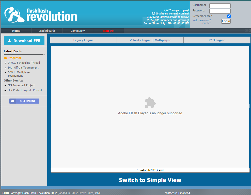
I then had the Makey Makey enter arrow keystrokes into my computer in order to play the online Flash Flash Revolution game!
I wasn’t very good about documentation back then, so unfortunately I don’t have any footage of me dancing.
And with Flash Player now defunct, I can’t even piece together that original setup to get a video :(

But that’s enough reminiscing! Back to the present project.
As this is another longer and more involved build, I may present items here in a different order than they were chronologically worked on.
It’ll be mostly unchanged, but if I decide reshuffling certain things will make them easier to understand, then I’ll do that! Just a heads up.

In broad strokes, Team BRUH planned to run Stepmania (an open-source DDR clone) on a Raspberry Pi computer, and stream it to a TV. For user input, we chose an array of load cells underneath each arrow pad, to sense when they are stepped on.
From there, a signal amplifier reads values from each array and converts them into a usable signal, which is sent to an Arduino. The Arduino converts the step pad data into keystrokes to send to the Stepmania, in addition to activating additional light and sound effects built into the platform.
I’ll go into more detail on each component later, just wanted to give an overview here.

Here is an early drawing of our envisioned design.
The dance platform would be a 3x3 grid, consisting of a wooden box skeleton with a plywood ‘skin.’ The arrow pads would have inset LEDs for visual effect, and load cells mounted underneath.
The aforementioned Arduino, Raspberry Pi, and other electronics all fit under the center panel, with output to built-in speakers for sound, and HDMI for video.
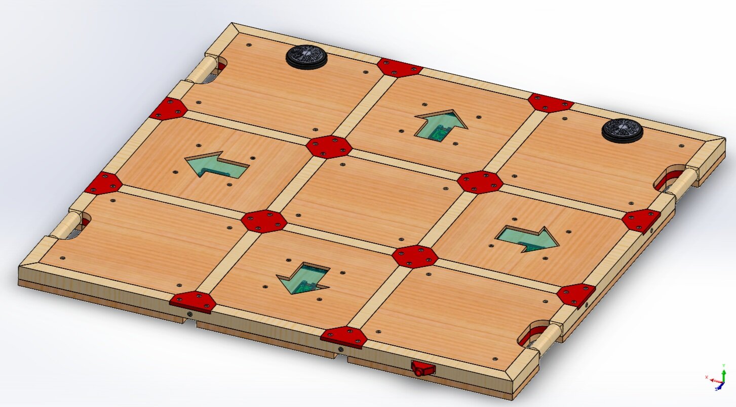
That design was eventually streamlined and simplified into the CAD model on the left!
The construction was modified to reflect commercially-available lumber dimensions. I decided to have the 4 arrow pads be floating as opposed to hard-mounted: supported from underneath by the load cells (so that all weight on the pad is transferred into the cells) and constrained from above by 3DP retaining plates (the red polygon pieces).
I also included cutouts in select body panels, to use the skeleton itself as carry handles!

Another CAD pic, looking up from below and with the base plate removed!
Everything colored red denotes a 3D-printed piece: load cell mounts, panel spacers, and a electronics tray in the center of the grid!

Additionally, instead of traditional printed/painted decals for the step arrows, I got a bit fancy and decided to use negative space instead.
The arrows would be cutouts, with an insert of LED edge-lit acrylic tucked into a pocket underneath for cool visual effect.

With a reasonable idea of what we were doing, we bought a few packs of cheap load cells for preliminary validation testing.

As the top and bottom surfaces of the load cell weren’t flat, we modelled a mounting bracket for it.
It also helped space the awkward gap between commercial lumber thicknesses.

A small note: Load cells are basically a strain gauge glued to metal. As such, they don’t directly measure load per se, but rather the deflection of metal geometrically arranged to deform under load.
As the strain gauge bends with the metal, its resistive properties change, and it’s those resistance changes that get interpreted as load values by the HX711 signal amplifier.
Coincidentally, the circuit we used for these load cells is the exact same Wheatstone bridge I used in my bike computer build!
Diagram courtesy of Indrek Luuk at Circuit Journal - was a big help and reference for this project!

We secured 4 load cells under a piece of scrap wood and wired up the Wheatstone bridge.
With the HX711 held in hand, and Arduino dangling precariously from a USB cable, Athena repeatedly stepped on the panel to apply load.
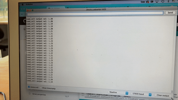
From the load values fed from the Arduino to the computer, we saw good results: The values obtained for the same amount of bodyweight applied were consistent between trials, and fell back to similar baselines when unloaded.
These values stayed the same even after disconnecting and reconnecting the load cells, HX711, and Arduino, so we called this first test a success!

Now onto the fun part, construction!
My roommate Eli (see Longhorn Open 2019 and Texas Strength Classic 2020 for more guest appearances 😂) and I made a trip to Home Depot to grab lumber.
The larger (4’ x 8’) sheet is MDF for the base panel, and the smaller one is nicer plywood for the visible top panels.
I asked the Home Depot workers to help cut the 4’ x 8’ sheet into 2 smaller 4’ x 4’ ones for easier transport.

Lumber naming conventions are weird.
You’d think a 2-by-4s would have a cross section of 2x4 in., but they actually end up being ~ 1.5x 3.5 in.! I understand the drying and planing process in making planks eats up material, but it’s still hard designing around that much imprecision.
But after looking around online, I found ‘dimensional lumber’ - wood cut true to size, presumably for decorative purposes. For whatever reason, they weren’t available in store, so I had some 1x1 in. square dowels shipped to my apartment.
These would make up the skeleton of the platform.
(Also peep Jotaro in the upper corner haha)

I’ve done enough woodworking to know that the number of operations for even a simple part can get out of hand quickly, and certainly would for this build.
To make the most efficient use of my shop time, I came up with a comprehensive laundry list detailing every single action, and the order to do it in - rough cut, cut to size, cut shoulder, mark holes, drill holes, countersink holes, etc.

First, I table sawed all pieces to their rough dimensions.
I laid them out here to label panels and just visualize things.

I mentioned earlier using 3D-printed retaining plates to prevent panels from falling out.
However, because I didn’t want these to protrude from the top of the platform, and possibly catch users’ shoes while dancing, I had to cut notches and shoulders into the skeleton segments so these could sit lower and be flush with the top surface.
I did this by using a chop saw incrementally along the length of the dowel. I used trial and error to find the hard stop setting that would give me a 1/4” cut (the random-looking cuts to the left), and once I had that limit dialed in, the rest was easy.
(CNC would have been overkill for a simple operation like this)


From left to right:
1) After that, I used a chisel to smooth out some of the ridges left over.
2) The shoulders and notches in corresponding dowel segments create a T-shaped recess where the corner brackets can rest and be bolted into.
3) A corner bracket / retaining plate / 3DP polygon (I’ve used like 3 different names for these pieces already lol) sitting in place.
At this point, you might be able to see how these work - the 45 degree overhang not resting atop the skeleton corresponds to a triangular shoulder in each wood panel, blocking them from falling out of the front of the platform.
For the step pads, this is the extent to how they are secured, but for the stationary (non-step) pads, there are additional mounting points (covered later).

I used the same chop saw method to cut channels on the bottom sides of the skeleton for for wire routing.
Also in this picture, you can see the triangular shoulders on some of the panels, and how they’d hook under the corner plates like I mentioned. These were cut on the chop saw as well.

Using a scroll saw to cut a rectangular hole into the skeleton, to run HDMI, aux, and power cables.

(From later in the build, but here are what the HDMI, power, and aux sockets look like)

Next, I marked and punched starter holes in the base plate to mount the skeleton to.
Because I almost always forget my punch at home, and I happened to be working with wood (soft MDF at that) instead of metal for this project, I took a driver bit and slammed a hammer into it to achieve the same effect.
Because this panel was too big to wrestle into a drill press, I propped it over 2 workbenches instead, and hand drilled each mounting hole.

Then, to perfectly transfer those hole locations to their corresponding skeleton segments, I used clamps to secure the dowels in place, then lightly drilled through the existing hole to leave a mark on the dowel.
Because I didn’t want any visible holes on top of the dowels, I used the hard stops on the drill press to carefully cut them to 3/4” deep.
The base plate holes got countersunk too.

With the skeleton fixed in place, now was the time to fix the inevitable tolerancing errors I had accumulated. Most, if not all, of the panels previously cut to size no longer fit, and needed material taken off their edges.
(Also note how the panels look ‘sunken’ relative to the main skeleton; this will be addressed later)

To ensure uniformity, I used double sided tape to fix panels together as ran them through the belt sander. I took off a tiny bit of material at a time, alternating sanding and test fitting until everything was snug.
At this point, the stationary panels were complete.

The step panels, however, needed one extra operation on the CNC machine.
Using a Shopbot 4x8 ft. CNC Router, we cut the arrow shapes and acrylic recesses in - we considered using laser and/or band sawing these, but this ended up being the best choice.

Freshly CNC’ed arrow pads! And on the reverse sides of the left- and rightmost panels, a recess for a square sheet of acrylic is visible as well.
I would have liked to make the arrows bit larger, but I already had concerns about weakening the wood too much (addressed later), and this was the most I dared push it.

Progress up to this point!
Everything fit together well, though some parts are just resting in place in this photo, and not actually screwed in yet.

And a pic of the underside!
I also ran the base board through the Shopbot, to make the carry handle cutouts, some 1/8” pockets in the corners (for our handrail!), and the square hole in the center for our electronics tray!

Leaving the carry handles with square corners was killing me, so I wasted some time lathing some rounded corners - much nicer to the touch 😊


To have the panel surfaces flush with the skeleton, I would need to raise them up an awkward 0.52401575 in. (🤢) - due to lumber sizing, as mentioned
It made more sense to 3DP rather than trying to machine material stock to those dimensions. I modelled some spacers to be glued to the base plate, with mounting holes to accept 8-32 bolts coming from the panels above.
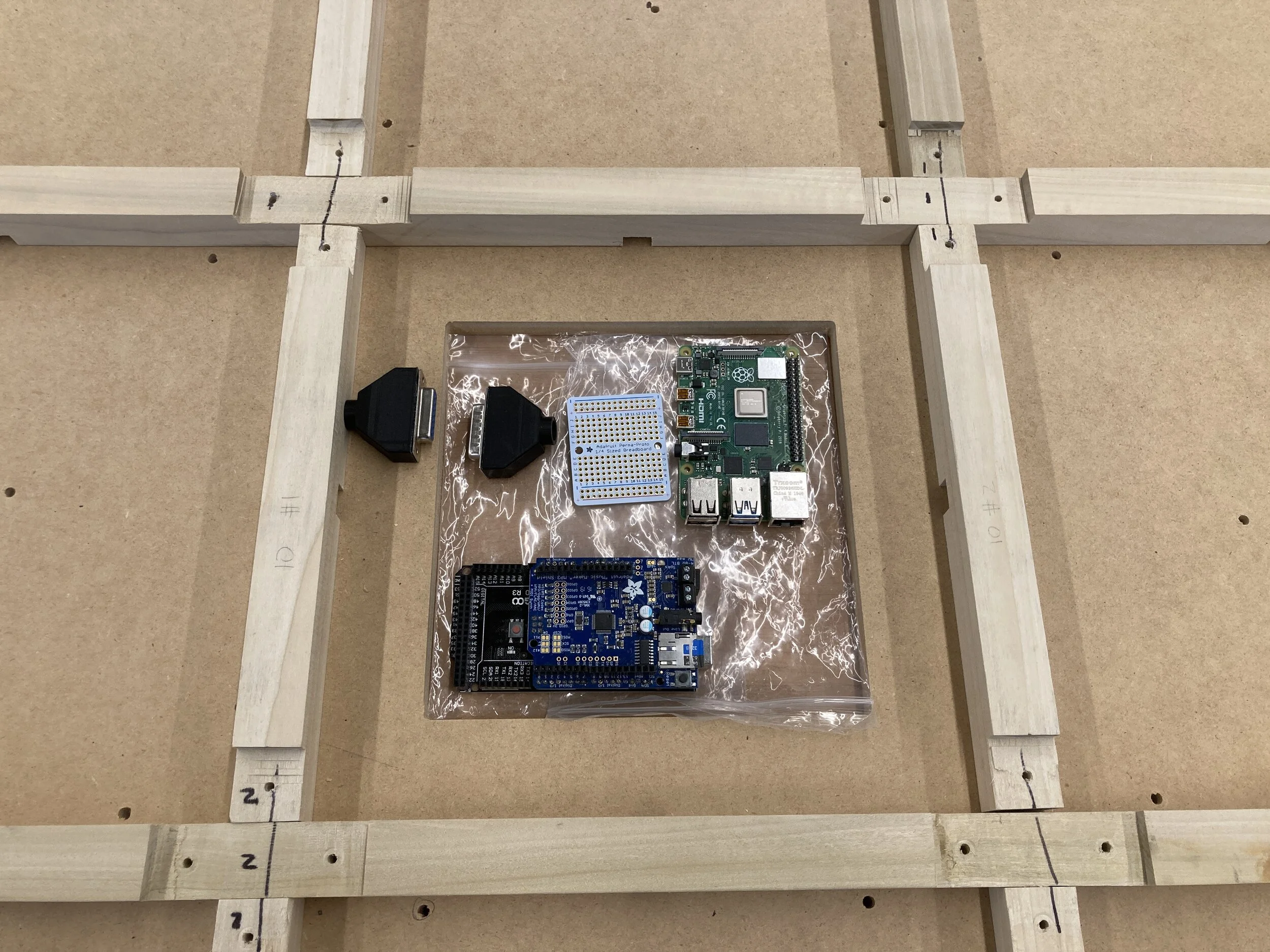
With most of the physical construction work in a good place, it was time to move onto electrical!
Here I am playing tetris, trying to find an efficient arrangement for our Arduino and Raspberry Pi, while taking account which direction wires would have to run, etc.
Also, because our chosen electronics were taller than the aforementioned 0.52401575 in. (🤢) gap, I decided to mount them on a tray suspended lower to the ground. By doing this, I earned back some overhead clearance.
(This took vague inspiration from oil pans being suspended below the engine in an automobile)

Here we are organizing which electronics and connectors go to which grid cells. You can also see the blue electronics tray!

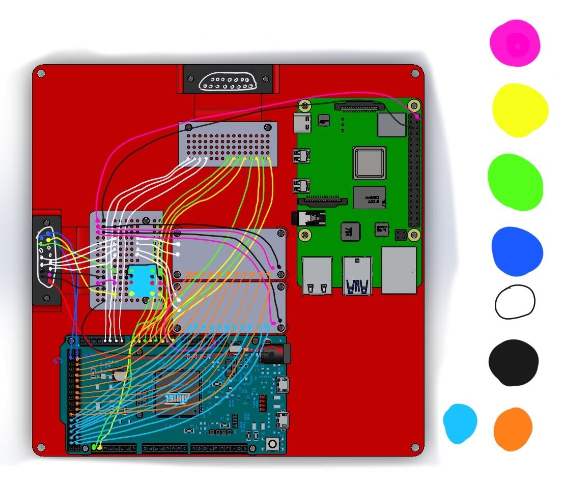
With those considerations in mind, I drew up a wiring diagram!
I tried to really optimize things here - for example, placing the HX711 amplifiers (small green boards) locally in their respective step pads cells, rather than them be centralized in the electronics tray, to reduce total yardage of wire needed (and $$$)!

Also sat down and figured out cable pinouts for the 7 DB15 connectors we’d be using throughout this project.
One thing I’ve learned is that the more color you can cram into a diagram, the better. (same goes for the above wiring diagram). It’s much faster when you’re actually wiring, because you can just glance at the printout and instantly recognize color, rather than having to squint and try to read tiny notation differentiating otherwise identical black squiggles.
Also, it’s prettier! 🌈

I spent an afternoon at home and soldered up the electronics tray!
Had to painstakingly crush the header blocks and desolder the pins so that everything could be directly hard-wired, but it was worth it.
Sadly, though I didn’t know it at the time, the Arduino Mega and Music Maker shield piggybacking on it would both need to be replaced. The Mega lacked Native USB for use as an HID device, and the Arduino Due we switched to wasn’t compatible with the Music shield :(
(discrepancy originally noticed by Athena - I skimmed and didn’t read carefully 😓)
Back at the workshop, Ryan and I worked on prewiring, cutting wire to length and routing it through the channels I cut in the skeleton.
We ate through an entire box of wire, so roughly ~138 ft? Jeez

I then soldered on appropriate connectors to the precut wire ends, and tried to bundle the wires to be a little cleaner.
Also:
DDR board says trans rights!

In the previous picture, some of the wire bundles were merely held down to the base plate using masking tape.
To better secure them, I modelled some anchor points that could be glued to the base, with wire fastened using zip ties.

Just a shot I thought looked cool - electronics tray hooked up to the main platform!
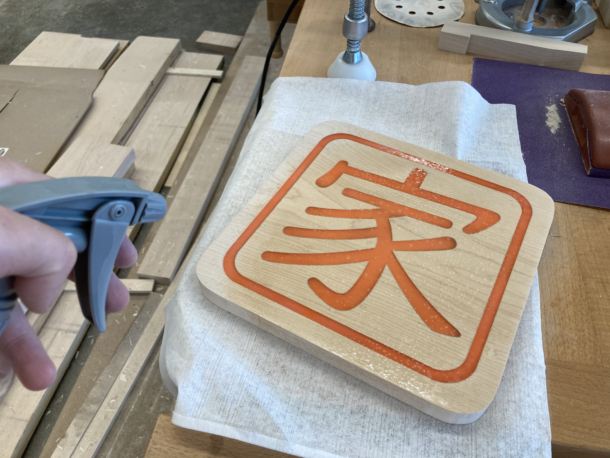
At the same time this was going on, Hope and I worked to seal the panels, so players wouldn’t leave nasty sneaker marks on the bare wood.
All the panels were uninstalled anyway, so during breaks from wiring, I went over to the paint booth to spray clear lacquer.


One thing that I didn’t do in this project was ‘popping the grain’ before painting.
I didn’t know about it then, but it’s good to do, so I’m including the process from another mini-project I did.
Popping the grain is a a step you’ll want to do before finishing any wood piece. After sanding, your wood will feel really smooth and you might be tempted to spray paint right away.
Instead, you should spray on a 1:1 water:alcohol mix first.
Wood grain expands from absorbing liquid, so even seemingly smooth wood can absorb paint and expand back into a rough finish. What spraying water+alcohol does is pre-emptively expand (or ‘pop’, like popcorn) the grain so that it can be sanded back down before actual paint.
Alcohol helps speed up the evaporation, but water delays the drying long enough to ensure the wood has enough absorption time.

It’s actually quite smart!

Laid the panels out in the paint booth and sprayed thin coats of clear lacquer every ~20ish (? - I don’t quite remember) minutes.

As long as I was already painting, I figured I’d get the skeleton as well, so we unscrewed everything and clear coated it as well.

Here is the platform all painted up to a nice sheen (& :O it’s Athena!)

As paint and wiring were done, we transitioned back to working on the step pads themselves, namely populating the interior with LED strips and bolting in the acrylic inserts.
Because the acrylic sheet (and recess designed for it to sit in) were thinner than the width of our LED strip, we actually had to trim away the edges of the strips to make everything fit.

Basically just took scissors and cut along these lines, right up against the solder points for the individual LEDs.

Because the material was so thin around the arrow cutout, I especially worried about deformation at the circled points. Those areas flexed even from just force from my fingers.

While some of the material cut out would be physically filled back in and reinforced by the acrylic insert, considering acrylic’s brittleness and weakness to bending, I wasn’t comfortable with leaving things that way.
(Even if it was me who designed it that way - shhhh!)


To fix this, we ordered some 1/8” aluminum plate to use as reinforcement. Band sawed to size, mocked up and marked reference points, then drill pressed and deburred bolt and cable holes.
You know the drill (heh) by now.


One complication came with using these plates with the trimmed LED strips mentioned earlier. The exposed solder points were isolated in the previous setup, but with the addition of a conductive aluminum plate, came risk of touching and short circuiting the strip.
This actually wasn’t an oversight, but something we had foreseen and already planned for. I:
1) scuffed the plates for spraying,
2) applied a coat of plasti-dip, then
3) threw on a last coat of matte white paint.
The plasti-dip covered the bare metal with an rubberized insulating layer to avoid contacting the solder points, and the white paint helped both protect the rubber layer, and reflect the light out of the arrow cutout!

Underside view of plate (and load cells + mounting brackets) installed!

Our efforts paid off! A very pleasant effect, I think

Next - Rail!
No DDR platform would be complete without a handrail!
Many commercially available platforms actually have additional corner buttons to navigate game menus (think Start and Select).
However, as each additional step pad meant significantly more components and wiring for us, we decided it would be smarter to mount an electronics box on the rail with Start/Select buttons, as you can see in my sketch.

I left the rail out of the original CAD model because I wasn’t sure what I’d be able to find to use, or whether I’d be able to find anything at all!
Case in point: after deciding that welding school metal shop scraps together would look too jank, I ended up visiting a salvage yard, and cutting out the rail from a push cart.

Spraying paint stripper to get rid of that disgusting orange paint.
Wear pants and long sleeves while doing this; I didn’t, and got burned when liquid splattered onto my skin :(
I got about 90% of the paint off using the spray, then cleaned everything up with an angle grinder + wire brush attachment.

For the rail to stand upright, it needed something to stand on!
Here I am band sawing some 1/8” steel to use as feet.


From left to right:
1) Remember those 1/8” corner pockets we CNC’ed into the base plate? The idea was for the 1/8” steel feet to tuck under there, and be held down by the user’s weight while standing on the platform. Here I mocked everything up and tack welded the rail and feet in place.
2) Back onto the table for a full weld-out
3) Ryan helped spray paint the rail red, and Hope got the electronics box parts 3D printed out.

Pic of the control box, all painted up!
(Also guest appearance from our DC motor)

Next, it was time to work on software!
With so many elements to coax into cooperating, it was crucial to go slow and build the code up incrementally, while testing at each step. I've seen a lot of people write out huge chunks of code without regular testing, then - surprise, surprise - be completely stumped when things don't work.

To do this, I basically ran 5 mini 'experiments' - using bare minimum code designed to test the functional relationship between select elements. When I got two elements working together, only then would I add in a 3rd, 4th, etc.
I think it was a much smarter way to go about things.

This just about sums it up. Hello Deku

Stage 1:
The first step was to get the Stepmania program itself built and running on the Raspberry Pi.
This in theory wouldn't be hard, but as I had a lot of trouble building OpenCV for my autocannon project, I went in wary and expecting to troubleshoot.

Fortunately, I needn't have worried - I followed this Youtube video and got things working without any trouble.

Stage 2:
With the Raspberry Pi and Stepmania working together, next up was to add in an Arduino!
I built the pictured test tool to simulate the DDR platform. The 6 pushbuttons are stand-ins for the 4 arrow pads and 2 Start / Select buttons on the control box.
This let me test the Arduino alone, ignoring the load cells for now - just less variables to mess around with.

Using the tool, I wrote some code to use the Arduino as a controller, and successfully play Stepmania without a keyboard!
Another benefit of the tool was that I didn't have to lug the heavy platform all the way home on foot.

Stage 3:
Moving back towards the base of the pyramid diagram, I focused on the load cells again.
While we had done initial testing, we hadn’t tried using the load cells to actually trigger anything yet!
Here you can see some scrap wood (with load cells taped underneath), the small green HX711 amplifier, and the Arduino Due I mentioned we switched to.

Ran a basic test to use the load cells as a trigger for an Arduino action.
Even though this might seem brain-dead & obvious in that "of course it'll work," these small methodical tests are still important for when things do go wrong, and you're forced to sheepishly admit you assumed something would work but didn't actually test - speaking from experience 👀
These actions would eventually be the game controls, but in the meantime, lighting LEDs in different colors in response to loads (using Monster cans as standardized weights lmaoo) was a good visual indicator.

(I give yall so much product placement just sponsor me already Monster)

Stage 4:
With the load cell - Arduino action pairing confirmed, I wrote some code for the Arduino to send ASCII commands when the load cell readings exceeded a certain threshold. Added low-pass filtering to eliminate noise that these MEMS devices are susceptible to.
This was tested by USB-ing up to my laptop and outputting ASCII "X" characters into Notepad. The actual destination would be the Raspberry Pi, but for this test there wasn't any functional difference.

Relevant lol
Stage 5:
Finally, putting it all together!
Here is a short video of me, originally intended as an update to the team, navigating the Stepmania menu using only the load cells.
This shows the successful chaining of the elements as built up through these tests: The load cells readings are passed through the HX711 into the Arduino, which generates subsequent commands to USB into the Raspberry Pi, in order to control the Stepmania program.
That was a mouthful.

Basically me during testing, bonking the table

Shifting gears back to the electrical side once more:
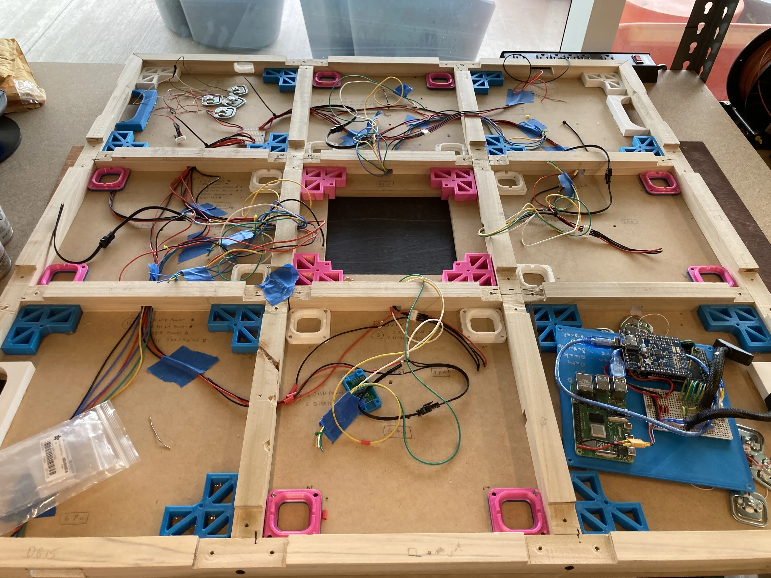
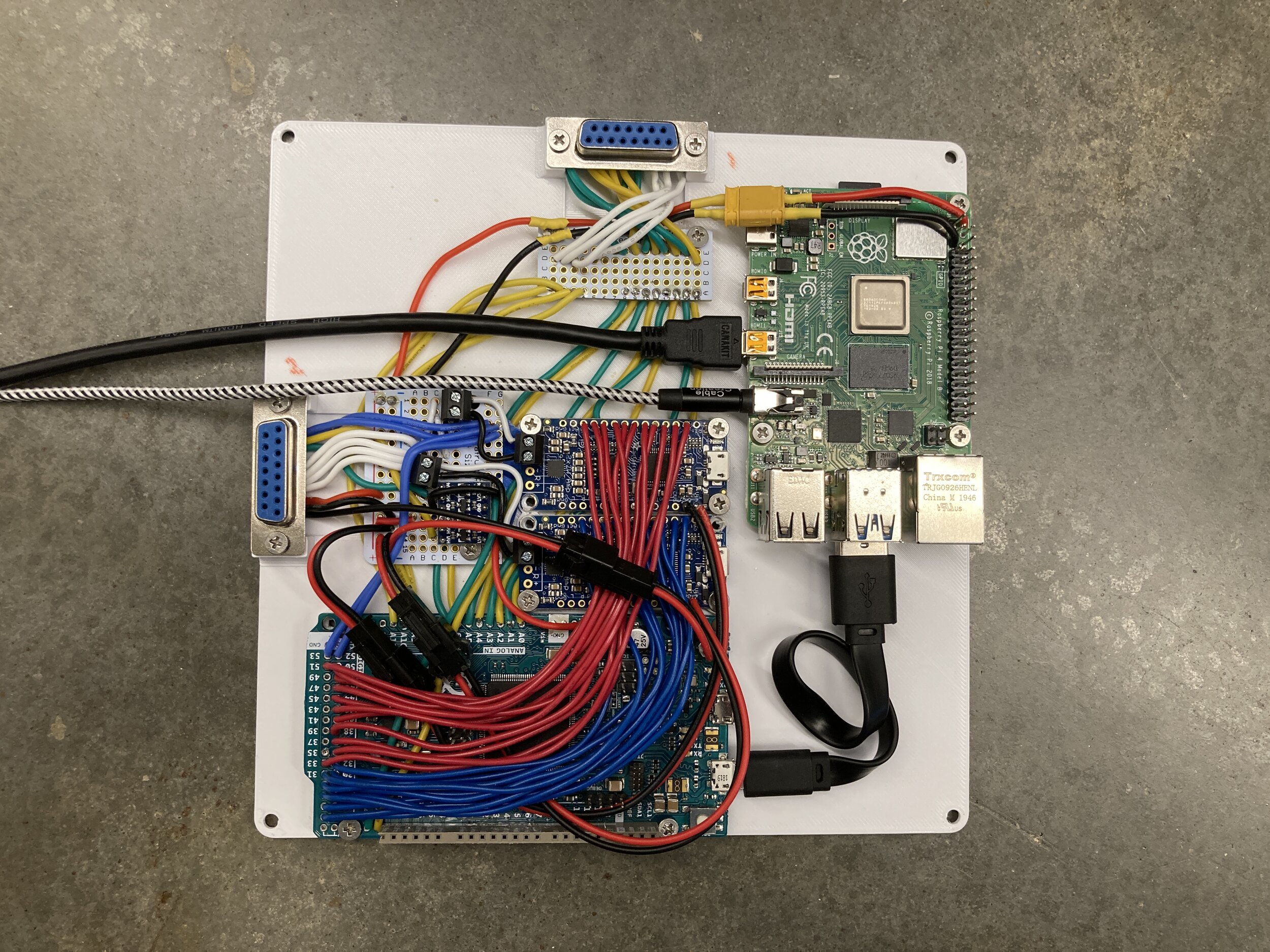
1) As the previous electronics tray no longer worked due to our Arduino changes, I drew up another one!
2) Halfway through wiring, with the attachment points showing how the tray will sit below the base plate surface
3) Several hundred solder points later - done, looking just like the diagram!

Demonstration of the electronics tray being fitted in place

Demo day was approaching fast, so we spent the last few nights really working hard!
One of last things we figured out were the speakers! We had gotten audio to play early on, but it was almost inaudible.
Took me a while to figure out a trace needed to be cut on the sound chip to increase gain and volume, and after that it worked great!
Ryan had prepared a bunch of Avatar sound clips, and somehow 'My cabbages' was the one chosen for test. I'm pretty sure I lost multiple IQ points from listening to it on loop all night.
Some last-minute playtesting. The last step was Athena and me tuning the threshold values for more consistency…

And then it was done! We packed everything up and hurried over to the classroom for demo day.
Everyone in the class got to come through and try out our DDR board!
It was a lot of fun!
(You can tell I’m sick of writing!)

Overall, I was very happy about our ability to crank something like this out in only 5 weeks (at the expense of my finals grades but whatevs).
I actually wasn’t that excited in the beginning, but got more and more into it as things went on, and got to enjoy the payoff along with everyone.
Some last supplemental items:
Here is an overview video Athena made as part of the assignment submission!
Basically going over the same things as this writeup

This was our project poster, as displayed on demo day…

And here were all the spare / unused parts we ended up with.


Thank you for reading! (And props for making it this far 😊)